
1
Define the Equipment Duty
Confirm condenser, evaporator, chiller, process cooler, seawater cooler or replacement bundle, and identify the tube-side and shell-side media.
Integral Low Finned Tubes in Stainless Steel and Titanium for Heat Exchangers, Condensers and Evaporators
GAOFA TECH supplies low fin tubes with integral external fins formed from the parent tube wall. Main material directions include stainless steel and titanium for shell and tube heat exchangers, surface condensers, evaporators, industrial refrigeration equipment, seawater cooling and corrosion-resistant heat transfer systems.
This page is the general selection and procurement guide. Use it to compare tube structures, material directions, integral-fin standards, geometry terms, inspection requirements and RFQ data before moving to the dedicated stainless steel or titanium low fin tube page.
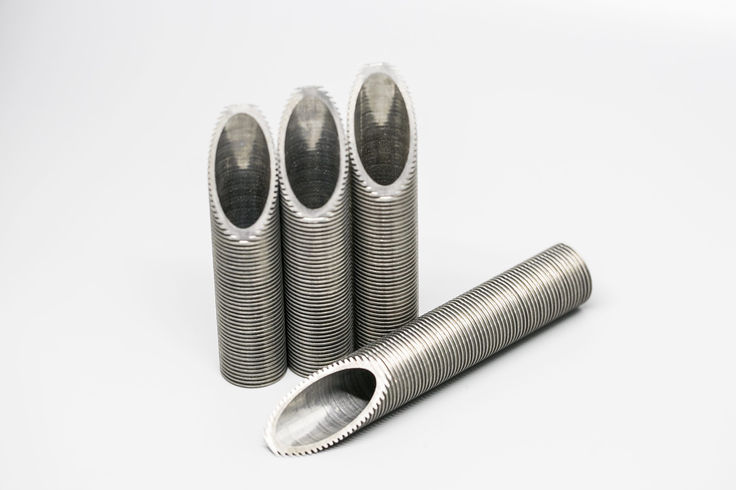
Typical dimensions below describe GAOFA TECH’s current review range, not a universal standard range or an automatic production guarantee. Final feasibility depends on material, parent tube condition, fin geometry, length, tolerances, quantity and inspection scope.
Fins are cold formed from the parent tube wall rather than attached as a separate fin strip.
Material selection starts with medium, corrosion mechanism, temperature, pressure and equipment approval.
Common base wall directions include 1.0, 1.1, 1.2, 1.5, 1.8 and 2.0 mm.
OD over fins, root OD, fin height, pitch, finned length and plain ends must be confirmed.
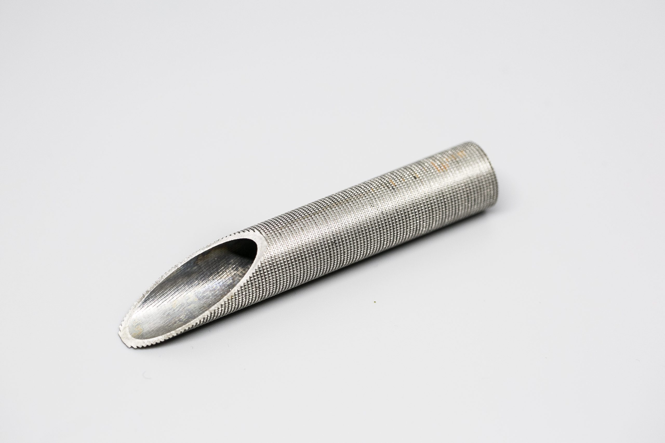
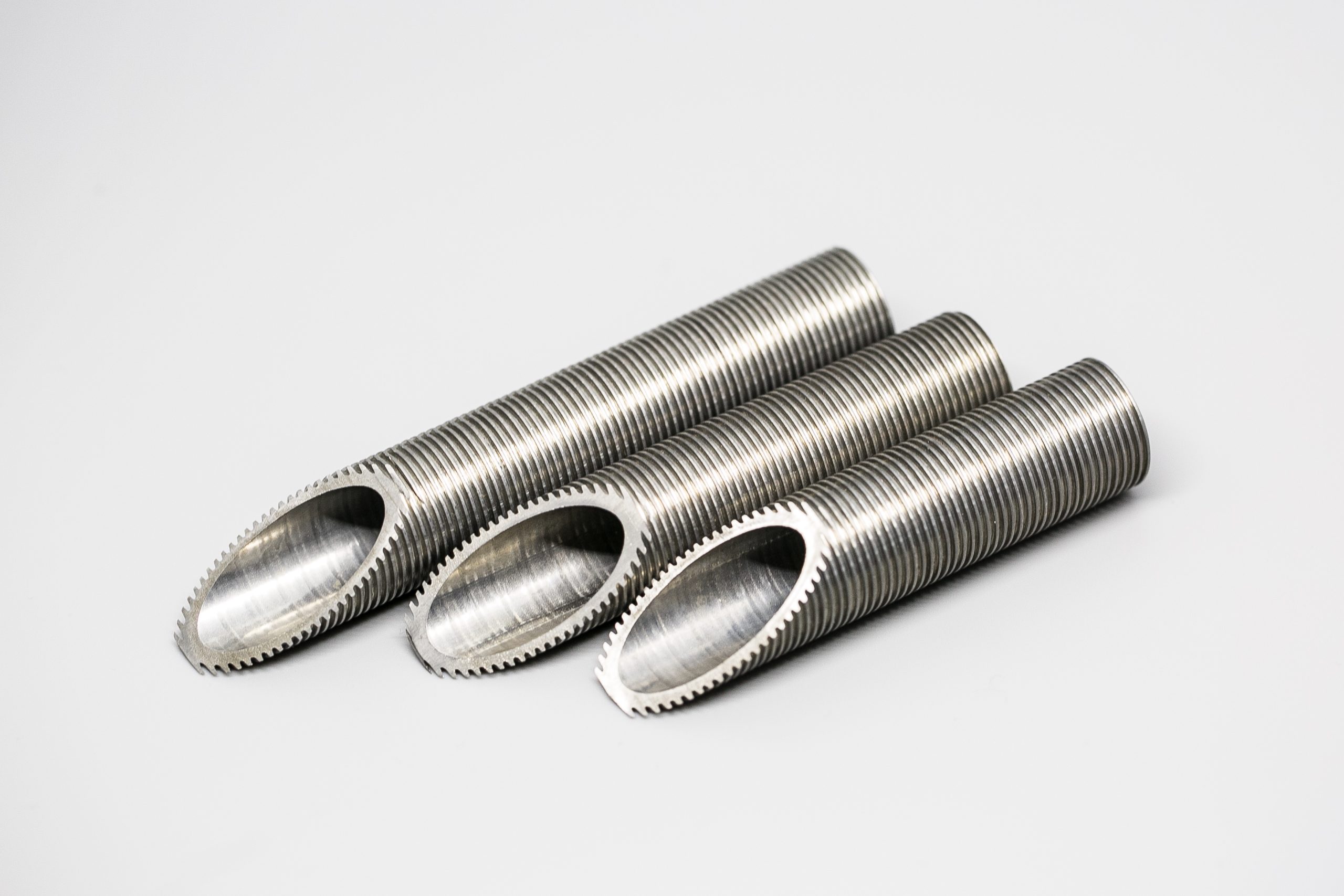
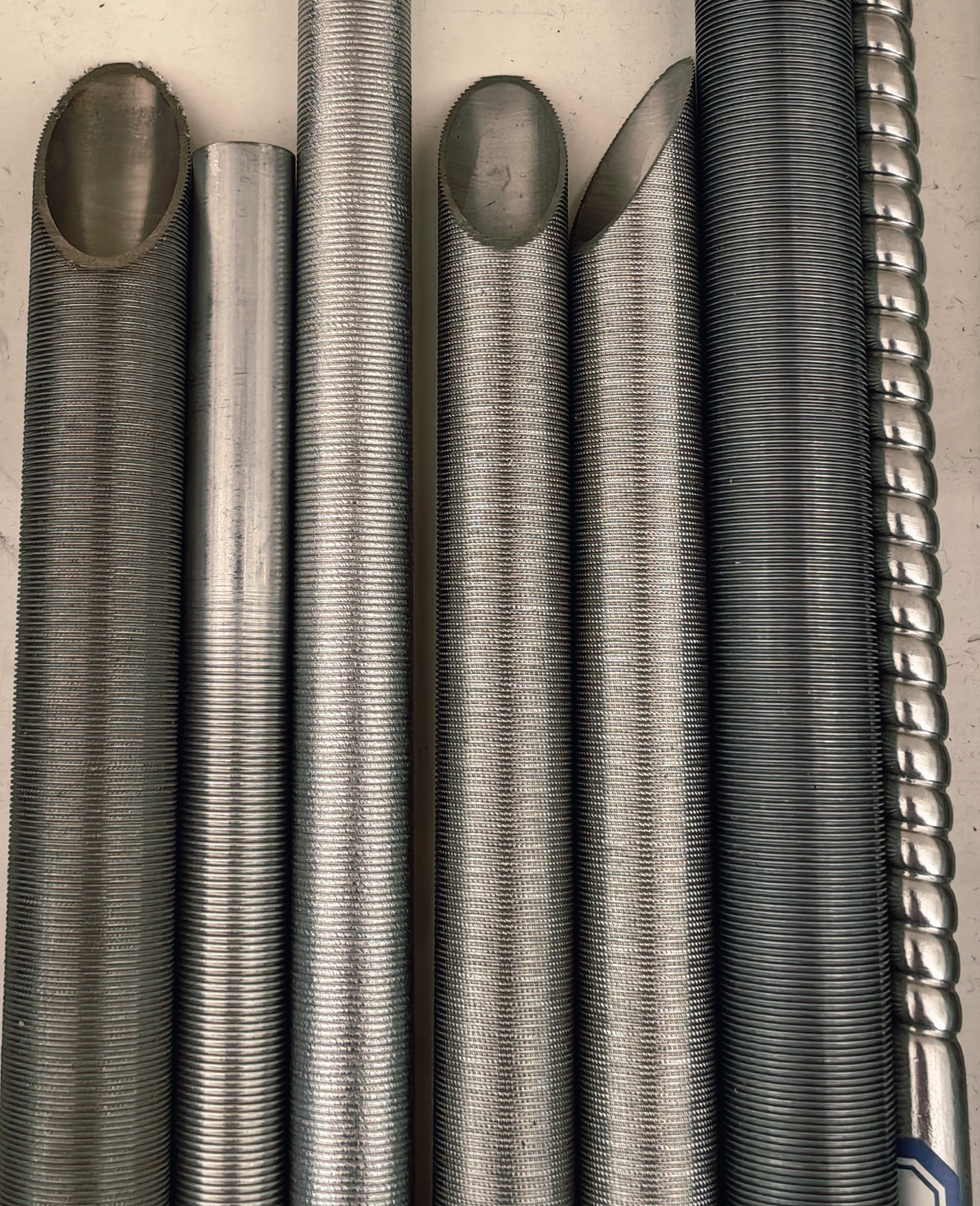
An integral low fin tube, also called a low finned tube or integral fin tube, is a heat transfer tube whose external low fins are produced by cold forming the wall of the parent tube. The fin and tube remain one continuous material structure, while one or both ends are normally left plain for tube sheet expansion, rolling, welding or sealing.
The purpose of the low fins is to increase external surface area. Whether that additional area improves actual equipment duty depends on the controlling heat transfer resistance, fin efficiency, shell-side fluid, condensation or boiling behavior, fouling, pressure drop, tube layout and cleaning method.
The buyer drawing should state the required construction. The phrase “finned tube” alone is not sufficient for quotation.
The correct selection sequence is thermal duty first, then corrosion and material, followed by geometry, fabrication and inspection. Starting only from material price or an existing tube name can lead to the wrong replacement decision.
Confirm condenser, evaporator, chiller, process cooler, seawater cooler or replacement bundle, and identify the tube-side and shell-side media.
External fins are useful only when additional outside area and the resulting fin efficiency support the thermal design.
Review water chemistry, chloride, pH, refrigerant, process medium, temperature, pressure, corrosion history and tube sheet material.
Confirm parent OD and wall, OD over fins, root diameter, fin height, pitch or FPI, fin thickness, finned length and plain ends.
Review baffle clearance, tube support, tube sheet connection, expansion or welding, mechanical cleaning and fouling tendency.
State the governing standard, base tube specification, tolerances, NDT, pressure test, documentation and packing requirements.
A low fin tube drawing should define the complete tube geometry rather than only the parent tube OD and wall thickness. The diagram below shows the main terms buyers and production teams should use when discussing an integral low fin tube.
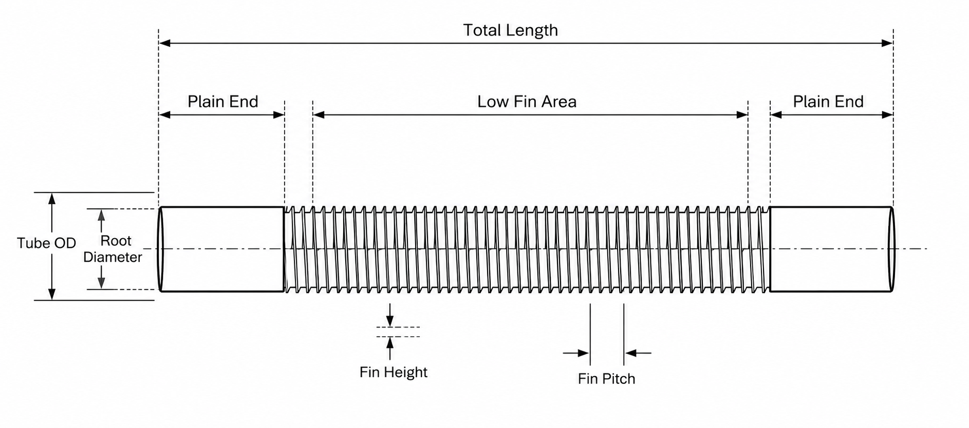
Total length is the finished end-to-end tube length. Plain ends are the unfinned areas generally retained for tube sheet expansion, rolling, welding, sealing or dimensional control. The low fin area is the axial portion containing the integral external fin profile.
Tube OD should be identified clearly as the parent or plain-end OD, while root diameter is measured at the base of the fin profile. The project drawing should also state whether another dimension is being used as the final OD over fin tips.
Fin height is the radial distance between the fin root and fin tip. Fin pitch is the axial spacing between adjacent fins and may also be specified as FPI or fins per meter.
“Tube OD × wall thickness” is not enough for an integral low fin tube quotation. Fin profile, end geometry and finished dimensional requirements directly affect tooling, forming feasibility, tube bundle compatibility and inspection.
This general page routes buyers to the correct material page. Detailed stainless grades and titanium grades are intentionally kept on the dedicated child pages to reduce keyword overlap and improve search intent clarity.
Reviewed for industrial heat exchangers, condensers, evaporators and refrigeration equipment where stainless strength, media compatibility or selected corrosion resistance is required.
Reviewed for seawater, brine, chloride-rich cooling water, marine condensers and selected corrosive heat transfer service. Grade, crevice condition and tube sheet design still require review.
Copper alloys remain common because of high thermal conductivity and established thermal designs. Stainless steel or titanium should not be presented as a drop-in replacement without thermal, corrosion and fabrication review.
| Material Direction | Main Reason for Review | Important Limitation | Best Next Page |
|---|---|---|---|
| Stainless Steel | Mechanical strength, industrial compatibility, selected corrosion resistance and copper replacement evaluation. | Lower thermal conductivity than copper; stainless grade must match chloride, temperature and corrosion conditions. | Stainless Steel Low Fin Tube |
| Titanium | Seawater, brine, chloride-rich water, marine cooling and longer-life corrosion review. | Higher material cost; galvanic design, crevice conditions, joining and end-user approval require attention. | Titanium Low Fin Tube |
| Copper / Copper Alloy | High conductivity and established HVAC, refrigeration and heat exchanger practice. | May face corrosion, erosion, ammonia compatibility, contamination or price-pressure concerns in some projects. | Copper Tube Replacement Review |
| Nickel Alloy / Other Alloy | Special corrosive or elevated-temperature service where common stainless or titanium routes may not fit. | Project-specific tooling, forming feasibility, minimum quantity, cost and standard availability must be confirmed. | Send project data for review |
A standard should be stated only when the order is designed and inspected to that standard. Material grade alone does not automatically make the finished low fin tube compliant.
Covers seamless and welded ferritic, austenitic and duplex alloy steel condenser and heat exchanger tubes with integral fins.
Confirm the latest required edition, governing parent tube specification, enhanced geometry, temper, plain ends, dimensions and tests.
Covers seamless and welded titanium and titanium alloy condenser and heat exchanger tubes with enhanced surfaces for improved heat transfer.
Confirm grade, parent tube route, external or internal enhancement, end condition, NDT, pressure testing and purchaser options.
The parent tube may also need to conform to an applicable stainless steel or titanium tube standard named in the drawing or purchase specification.
Examples may include heat exchanger, general-service or titanium condenser tube specifications, but the buyer must confirm the exact standard.
Application suitability depends on actual thermal design and service conditions. The cards below explain the purchasing logic rather than claiming universal performance improvement.
Reviewed when greater outside surface area is needed within a defined tube bundle, baffle and cleaning arrangement.
Used in selected condensation duties where fin geometry, condensate behavior, fouling and tube layout have been thermally validated.
Reviewed for selected evaporation and refrigeration duties according to refrigerant, boiling regime, oil return, pressure drop and equipment design.
Applicable to selected condenser, evaporator, chiller and process cooling equipment where integral fin geometry is specified.
Titanium low fin tubes may be reviewed where seawater corrosion resistance and external enhancement are both required.
The original drawing, tube sample, failure history, tube sheet details and required duty should be supplied before matching or changing the tube.
These tube structures solve different thermal and maintenance problems. A design may also use combined enhancement, but only when the drawing and production route are specifically confirmed.
| Tube Structure | Where the Surface Is Changed | Main Design Purpose | Key Procurement Question |
|---|---|---|---|
| Smooth Tube | No intentional internal or external enhancement. | Standard heat transfer, simpler cleaning, broad standard and fabrication options. | Is a standard surface sufficient for the required duty and lifecycle? |
| Integral Low Fin Tube | External low fins formed from the parent tube wall. | Increase external area in suitable condenser, evaporator or shell-side designs. | Is outside heat transfer resistance important, and can fouling and cleaning be managed? |
| Inner Grooved Tube | Internal helical or structured grooves. | Increase internal area and influence tube-side flow, turbulence or refrigerant behavior. | Does the tube-side duty justify added pressure drop and a defined internal geometry? |
| Internally and Externally Enhanced Tube | Both internal and external surfaces are modified. | Address both sides of the thermal resistance in a purpose-designed exchanger. | Is the combined profile supported by drawing, tooling, inspection and thermal validation? |
Inspection should cover both the parent tube and the final enhanced profile. The agreed inspection plan should be stated before production because NDT and pressure-test requirements affect process route, lead time and quotation.
| Control Stage | Typical Check | Why It Matters |
|---|---|---|
| Material and Traceability | Grade, heat number, MTC, chemical composition and PMI when specified. | Confirms the parent material and maintains order traceability. |
| Parent Tube | OD, wall thickness, straightness, weld condition where applicable, surface and initial NDT status. | Parent tube variation can affect final root diameter, remaining wall and fin consistency. |
| Integral Fin Forming | Fin profile, continuity, fin pitch, visible damage, transition zones and forming stability. | Controls geometry repeatability and prevents unacceptable fin deformation. |
| Final Dimensions | OD over fins, root diameter, fin height, finned length, plain ends, total length and straightness. | Ensures tube bundle, baffle and tube sheet compatibility. |
| NDT and Leak Testing | Eddy current, pneumatic, hydrostatic or other agreed methods; UT only when specified and technically applicable. | Confirms tube integrity according to the governing standard or purchase specification. |
| Cleaning and Packing | Surface cleanliness, end protection, separators, bundle protection, wooden case and packing records. | Protects fin tips, plain ends and tube surfaces during handling and international shipment. |
Review GAOFA TECH inspection examples for material verification, OD and wall thickness measurement, visual inspection, eddy current testing, pneumatic testing, ultrasonic testing where applicable, cleanliness review and packing protection.
A drawing is strongly recommended. For a replacement tube, also send the original tube sample or dimensional report, equipment position, failure mode and whether thermal performance must remain unchanged.
GAOFA TECH can review an incomplete inquiry, but the quotation should not be treated as final until the fin profile, plain ends, material route, inspection scope and applicable standard are confirmed.
Copy this short template and send it with your drawing or sample information.
Fastest quotation route: send a PDF drawing plus material grade, quantity, total length, application, medium, temperature, pressure, required standard, inspection plan, destination and delivery target.
Please send the parent tube size, material grade, OD over fins, root diameter, fin height, pitch, finned length, plain ends, quantity, working media, temperature, pressure, inspection requirement and delivery destination. For material replacement, include the original tube drawing and the reason for the change.
A low fin tube is a heat transfer tube with low external fins. In an integral low fin tube, the fins are cold formed from the parent tube wall, increasing external surface area while normally leaving plain ends for tube sheet connection.
An integral low fin tube forms the fins from the parent tube wall, so the fin and tube are one continuous material structure. Applied fin tubes use a separate fin strip or sleeve attached to a base tube by wrapping, embedding, welding or another joining method.
No. Additional area can support heat transfer, but actual duty depends on overall heat transfer coefficient, fin efficiency, shell-side and tube-side film coefficients, temperature difference, flow distribution, fouling, pressure drop and equipment design.
ASTM A1012 is a common direction for ferritic, austenitic and duplex alloy steel condenser and heat exchanger tubes with integral fins. ASTM B891/B891M is a common direction for titanium and titanium alloy condenser and heat exchanger tubes with enhanced surfaces. The required edition, parent tube standard and purchaser options must be confirmed.
Please provide parent or plain-end OD, base wall thickness, OD over fins, root diameter, fin height, fin thickness, fin pitch or FPI, finned length, plain end length, total length, tolerances and quantity. A drawing or original sample is strongly recommended.
Both welded and seamless parent tube routes may be reviewed, depending on material, governing standard, size, wall thickness, fin geometry, pressure, fabrication process, inspection requirement and customer approval.
Plain ends provide controlled areas for tube sheet expansion, rolling, welding, sealing, dimensional measurement and assembly. The required plain end length and transition profile should be stated on the drawing.
Stainless steel low fin tube may be reviewed for industrial heat exchangers, condensers, evaporators and refrigeration equipment where strength, media compatibility, selected corrosion resistance or copper replacement evaluation is required. Grade selection depends on water chemistry, chloride, temperature and corrosion conditions.
Titanium low fin tube may be reviewed for seawater, brine, chloride-rich cooling water, marine condensers and selected corrosive heat transfer systems. Titanium grade, pH, temperature, crevice condition, tube sheet material, joining and galvanic design must still be checked.
They may be reviewed as alternatives when corrosion, erosion, media compatibility, contamination, strength, service life or copper price pressure becomes important. They are not automatic drop-in replacements because thermal conductivity, wall thickness, fin geometry, pressure drop, fabrication and equipment duty must be recalculated or approved.
A low fin tube changes the external surface and is reviewed for outside-tube or shell-side enhancement. An inner grooved tube changes the internal surface and is reviewed for tube-side flow or refrigerant-side enhancement. Selection depends on which side controls thermal resistance and on allowable pressure drop.
Inspection can include material traceability, PMI, parent tube OD and wall, OD over fins, root diameter, fin height, pitch, finned and plain lengths, visual inspection, eddy current testing, pneumatic or hydrostatic testing, cleanliness and packing review. The final scope must follow the order standard and agreed inspection plan.