
01 / Corrugation
Corrugated Tube
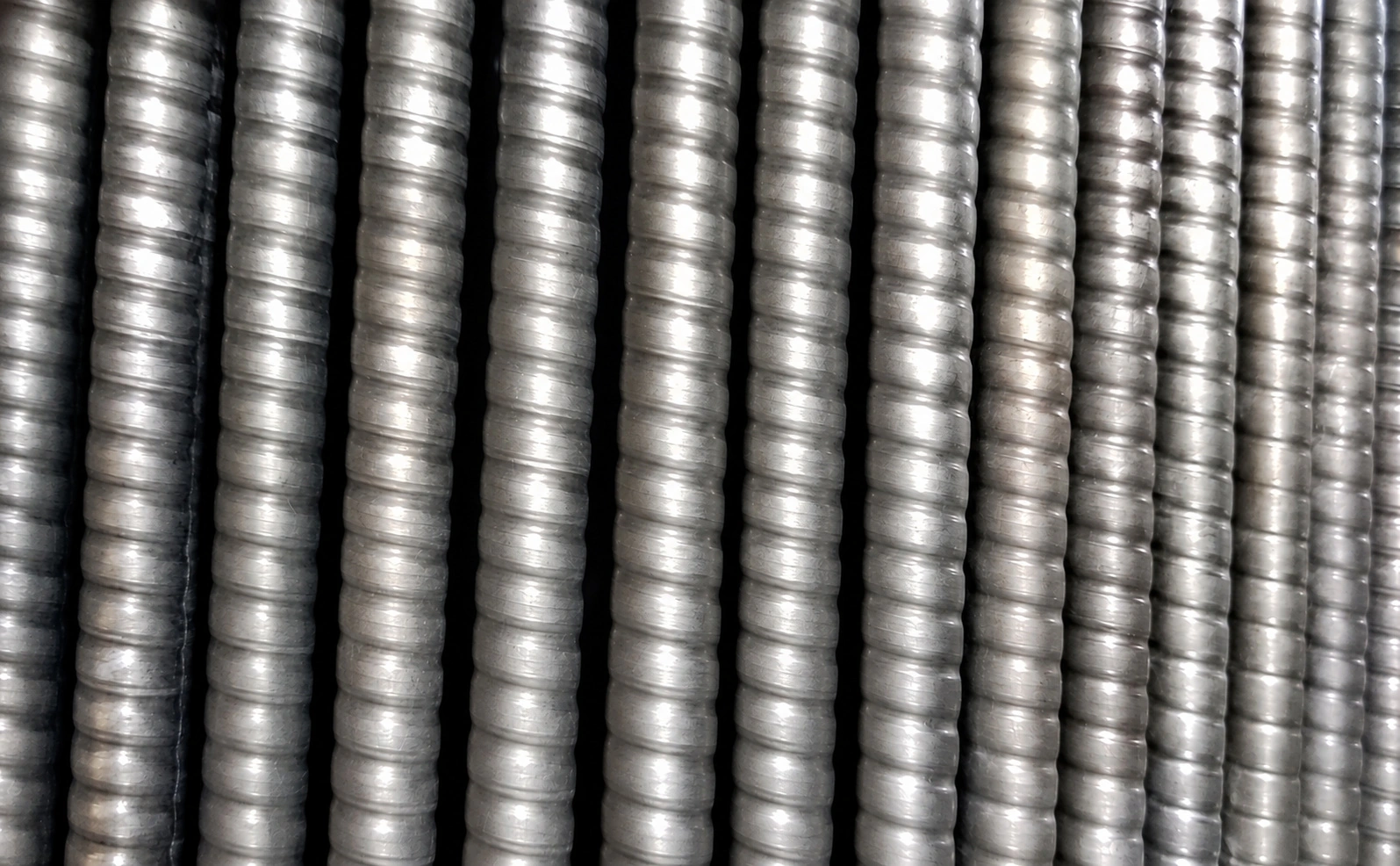
Axisymmetric formed corrugations change the surface geometry. The resulting inside and outside profiles and cleaning suitability depend on the finished drawing.
View Corrugated Tube →Internal, External and Combined Surface Enhancement for Heat Transfer Equipment
GAOFA TECH is a specialized enhanced heat transfer tube supplier, supporting inner grooved, low fin, corrugated and combined-surface designs through specification review, manufacturing coordination and export supply. For dual / double enhanced tubes, GAOFA TECH also has its own complete manufacturing capability for drawing-defined external fins and internal ribs. Explore six geometry families for heat exchangers, condensers and evaporators, refrigeration equipment and industrial cooling systems. Material, dimensions and manufacturing route are reviewed against each drawing.
Copper or copper alloy enhanced tube options can also be reviewed according to customer drawings, working medium, heat transfer requirement and project specification. Enhanced tube selection should consider heat transfer performance, pressure drop, fouling, cleaning method, material compatibility and equipment design.
This overview helps purchasing and engineering teams compare the enhancement side, geometry, material and inspection requirements before requesting a quotation. Equipment context matters: heat exchangers, refrigeration, marine cooling and copper replacement may call for different tube designs.
Inner grooved, low fin, corrugated, spiral corrugated, enhanced condenser and enhanced evaporator geometries are reviewed by drawing.
GAOFA TECH mainly supplies stainless steel and titanium enhanced tubes. Copper enhanced tube can be reviewed by project.
Catalogue low fin references include OD 7–38.1 mm. Feasible diameter, remaining wall and fin geometry depend on the material, tube route and drawing.
Inner grooved tube review should confirm tube OD, wall thickness, groove depth, groove angle, helix angle and application.
Enhanced heat transfer tubes are engineered tubes with internal grooves, external fins, corrugations or combined features used to improve heat transfer in selected heat exchangers, condensers, evaporators and refrigeration systems.
Their purpose is to address a specific heat transfer limitation, not just to maximize visible area. Inner grooves can alter tube-side flow and phase-change behavior; external low fins extend outside surface; corrugations alter formed geometry on one or both sides. Some condenser and evaporator designs combine external fins with internal ribs. The benefit depends on the actual fluid-side thermal resistance, geometry and operating conditions.
In international purchasing, enhanced tubes may also be called high performance tubes, high efficiency heat transfer tubes, inner grooved tubes, low fin tubes or enhanced heat transfer tubing. Actual performance still depends on tube material, groove or fin geometry, working medium, flow regime, pressure drop, fouling factor, cleaning method, tube-sheet connection and complete equipment design.
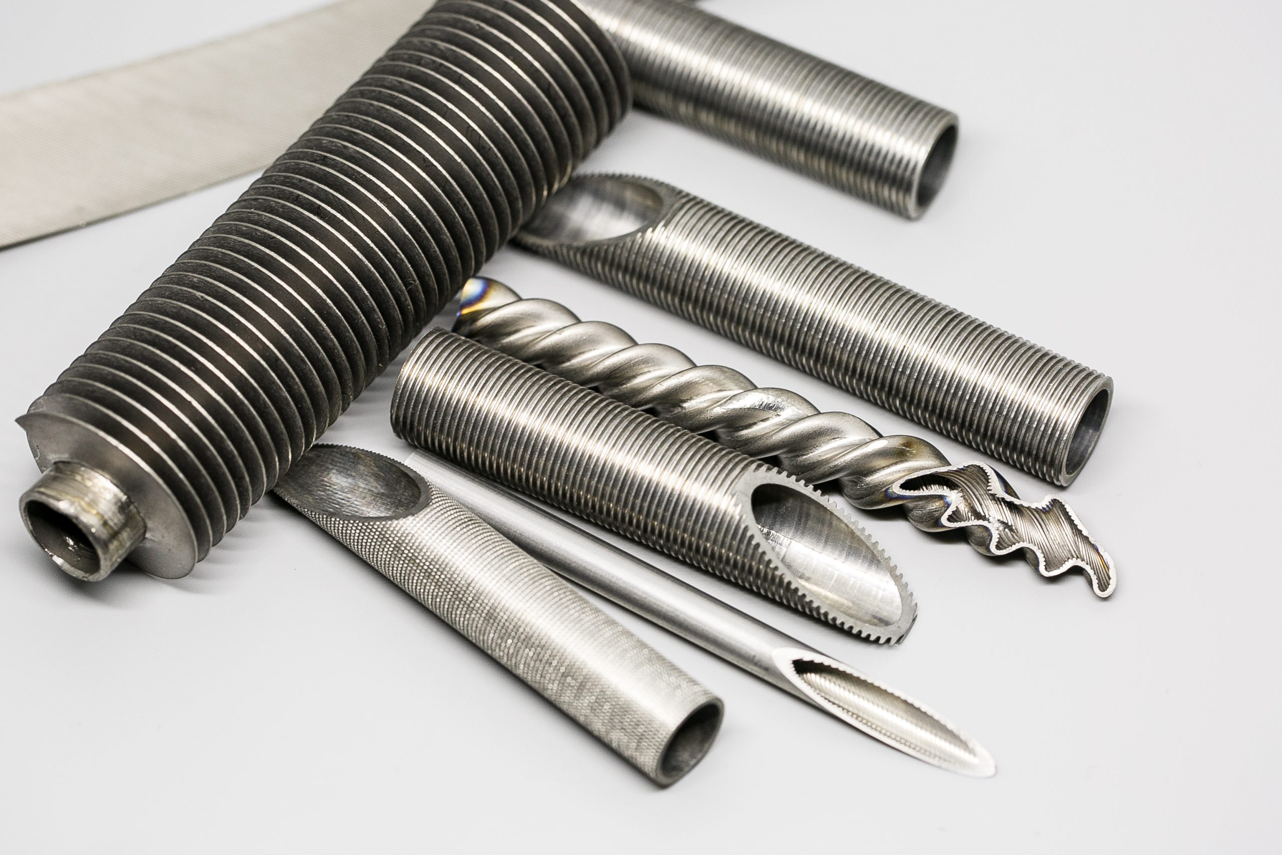
The six families below represent different geometric approaches. Some primarily change the inside surface, some the outside, and some both. An identical material is not necessarily available in every profile or manufacturing route; feasibility is assessed against the finished drawing.
Axisymmetric formed corrugations change the surface geometry. The resulting inside and outside profiles and cleaning suitability depend on the finished drawing.
View Corrugated Tube →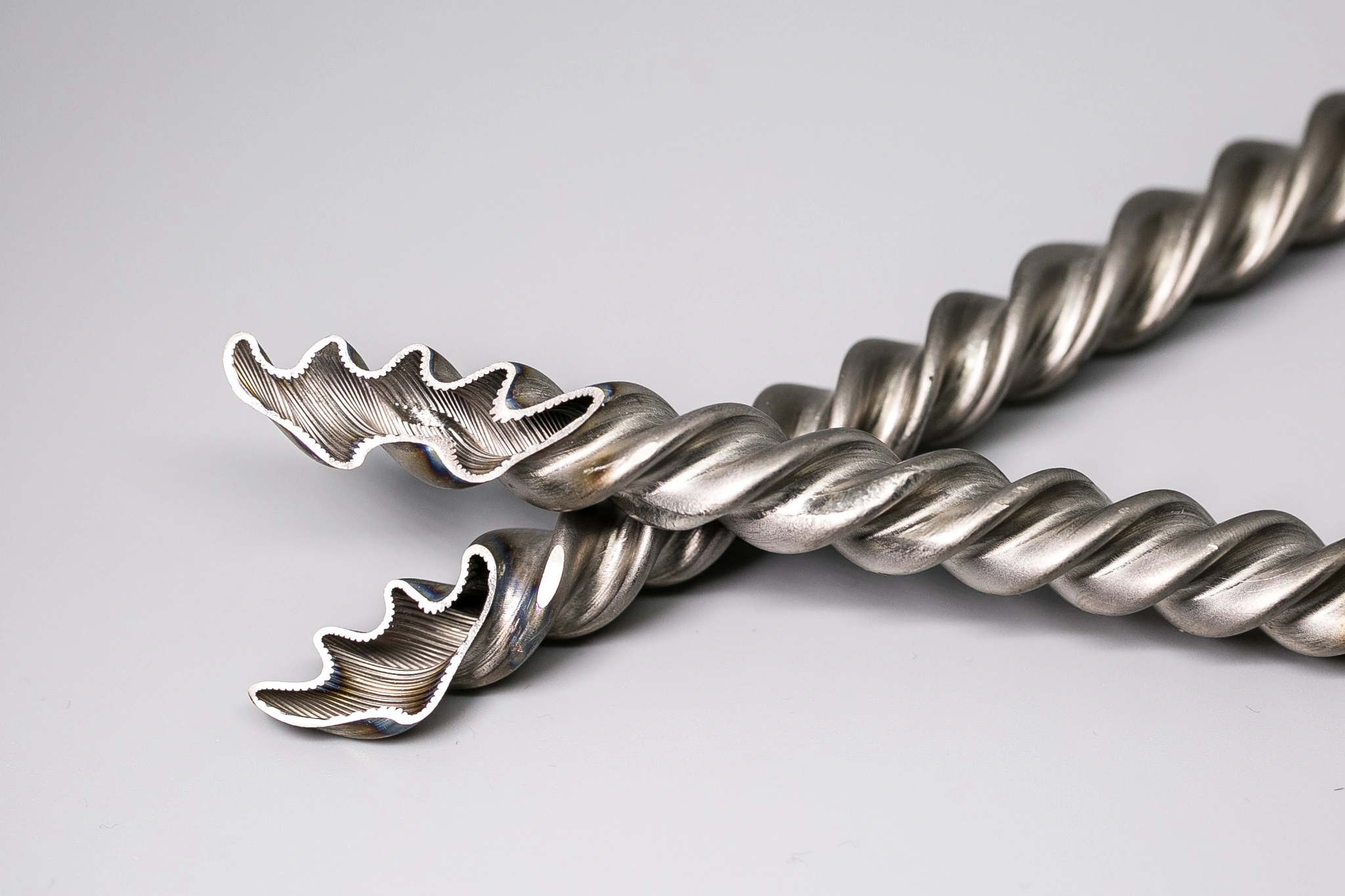
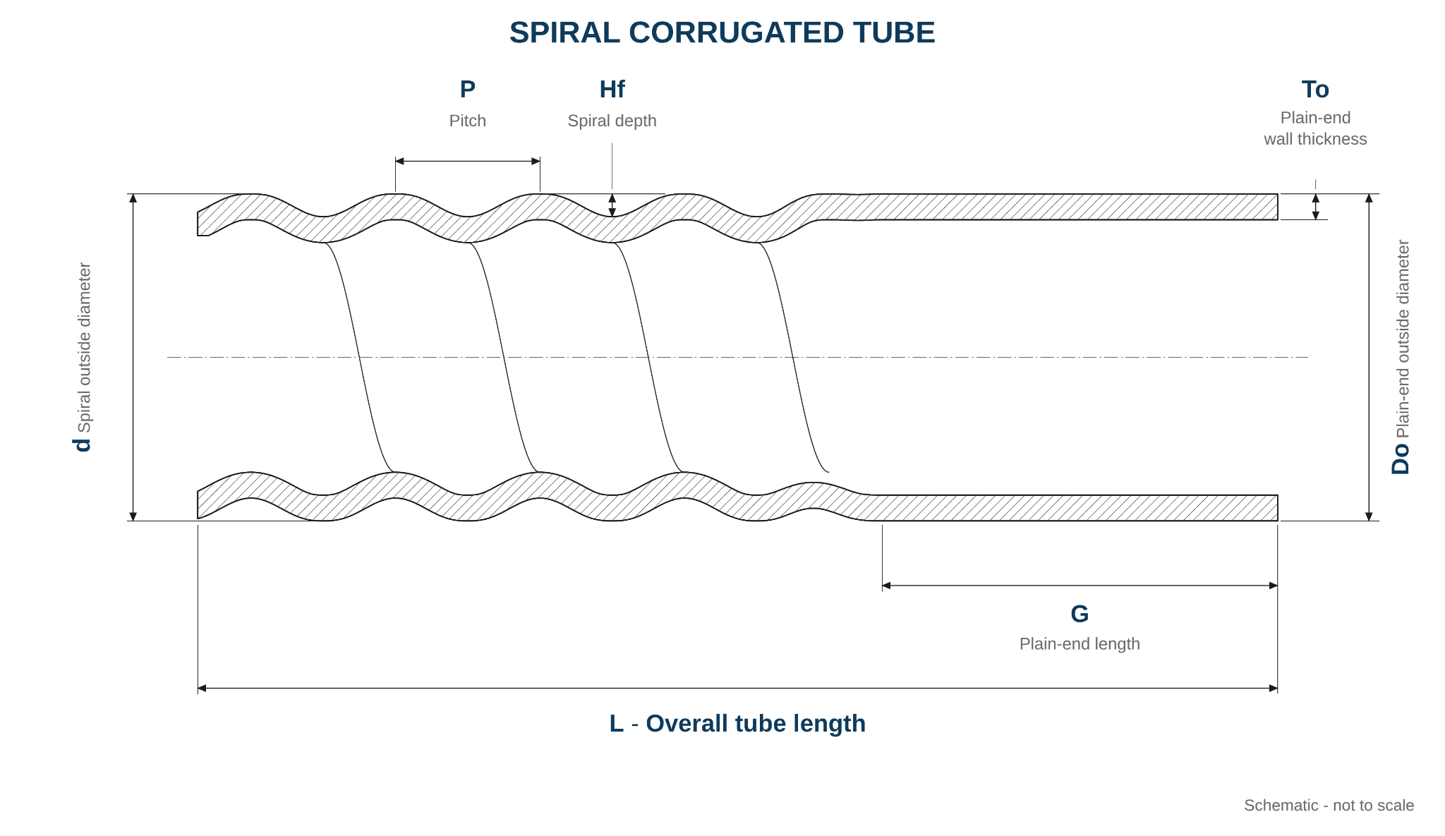
Multi-start helical corrugations introduce pitch, depth and start-count requirements. Confirm the dimensional convention and finished wall geometry.
Send Spiral Drawing for Review →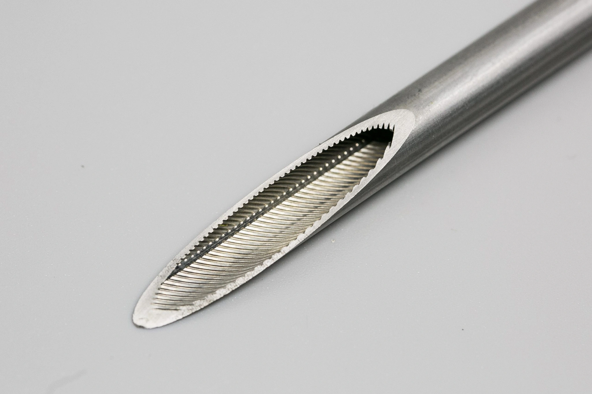
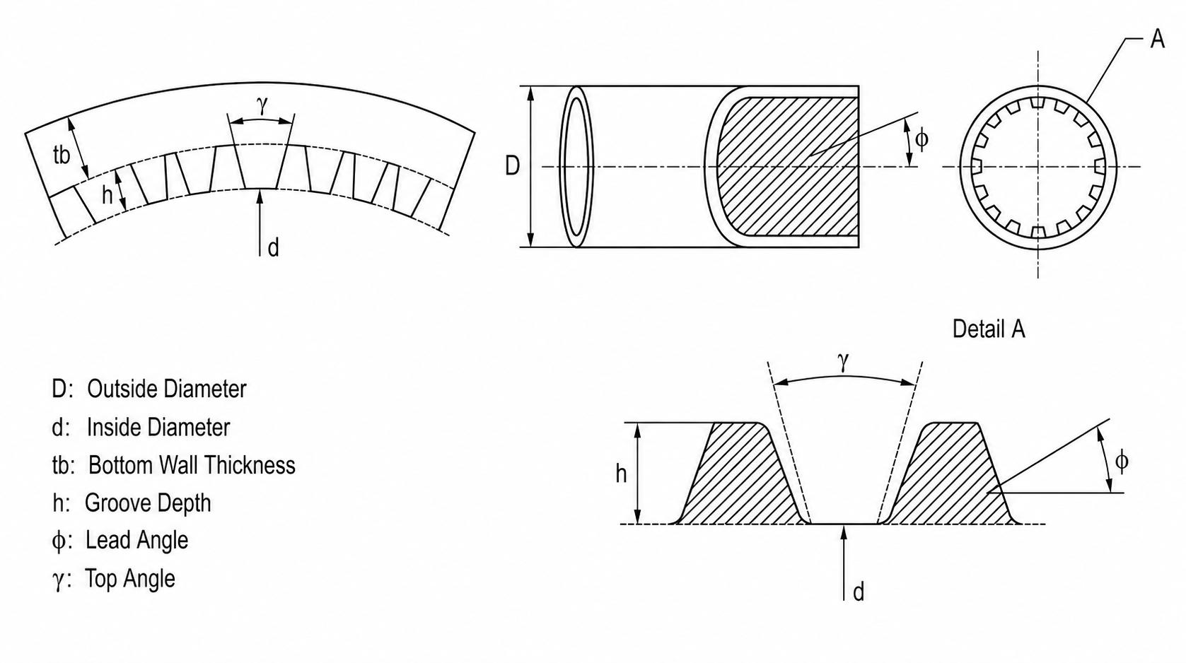
Internal helical ribs or grooves are used where tube-side flow or phase-change performance warrants a specific profile.
View Inner Grooved Tube →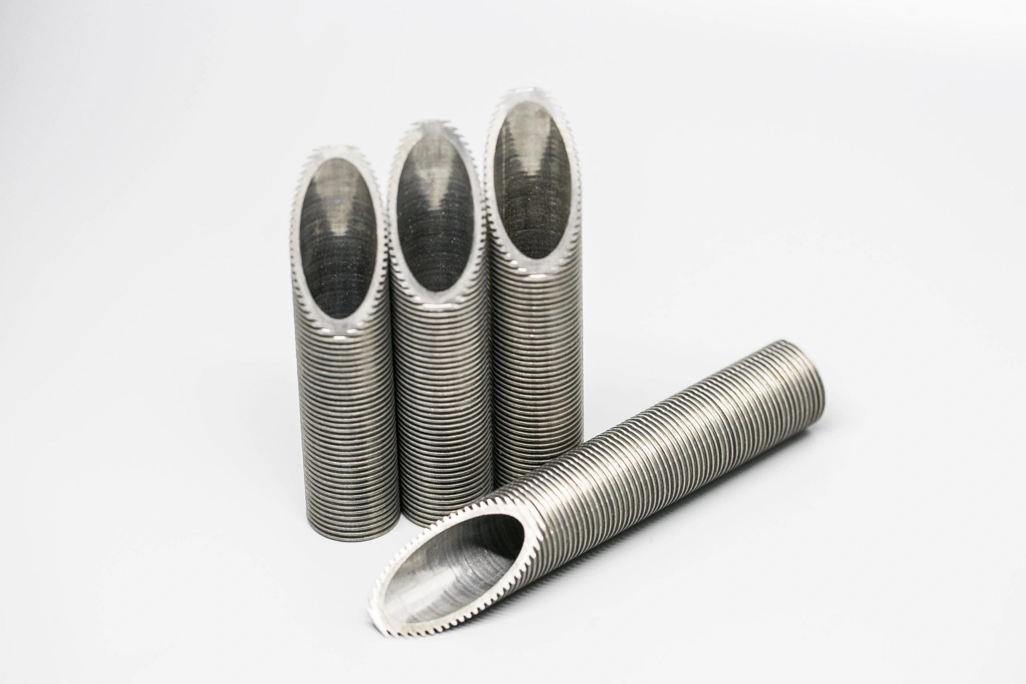
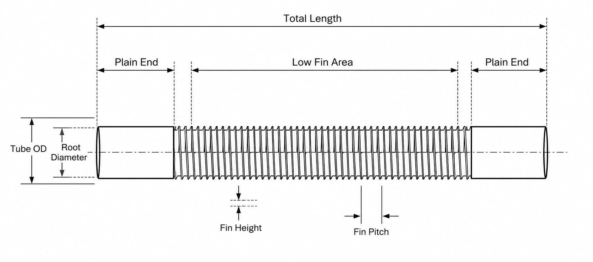
Integral external fins extend outside area. Fin-tip OD, root diameter, FPI and the plain ends are critical procurement dimensions.
View Low Fin Tube →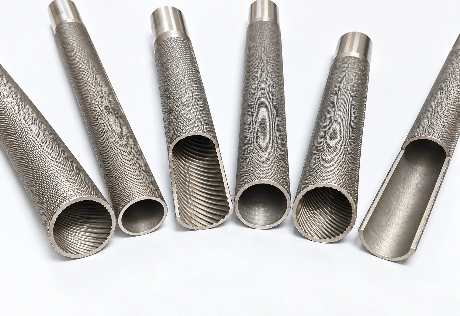
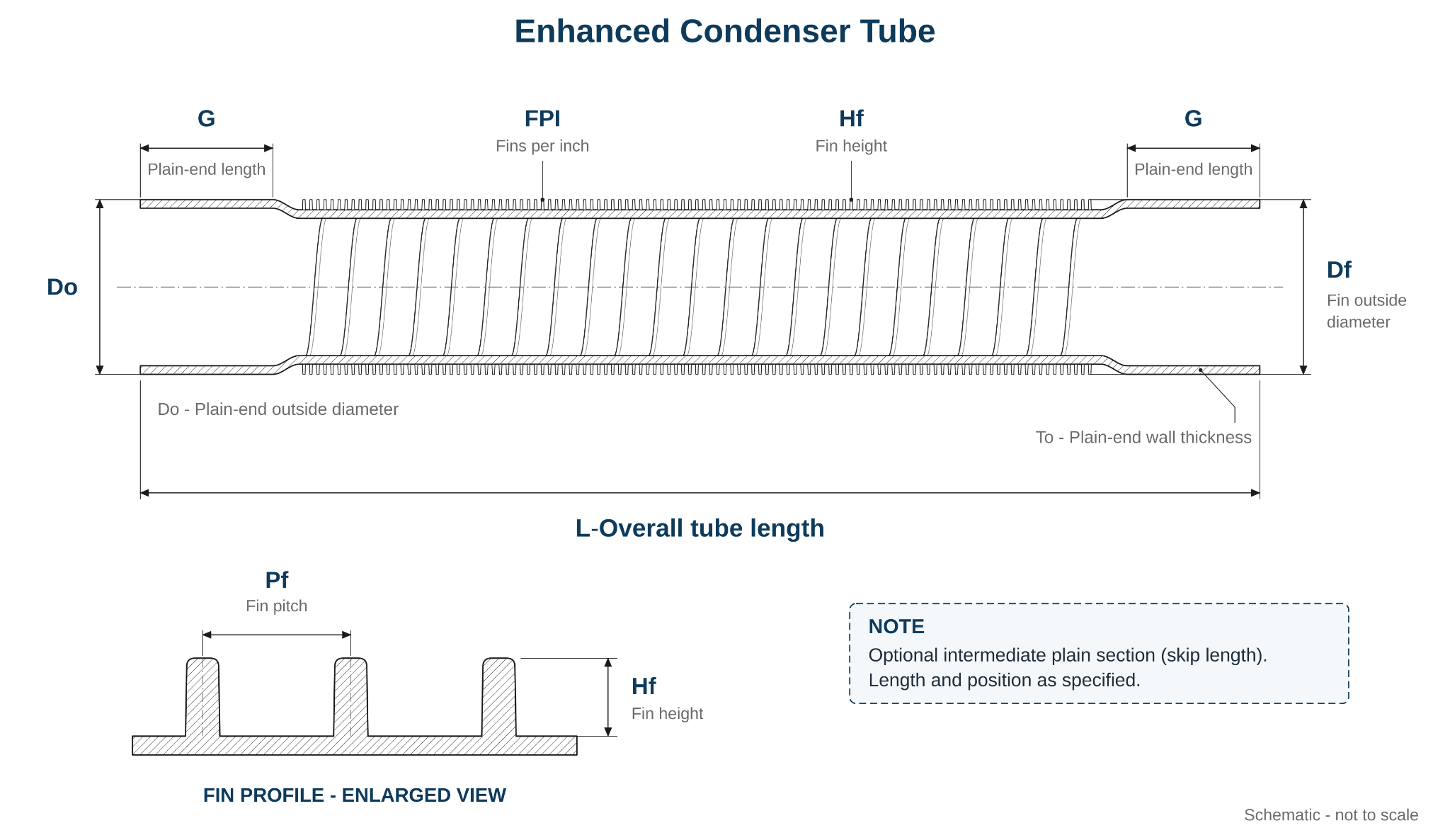
Condenser-oriented external fin geometry may be combined with internal ribs. Knurling and fin details require a profile drawing. For a true two-sided profile, see our dual enhanced tubes.
View Condenser Applications →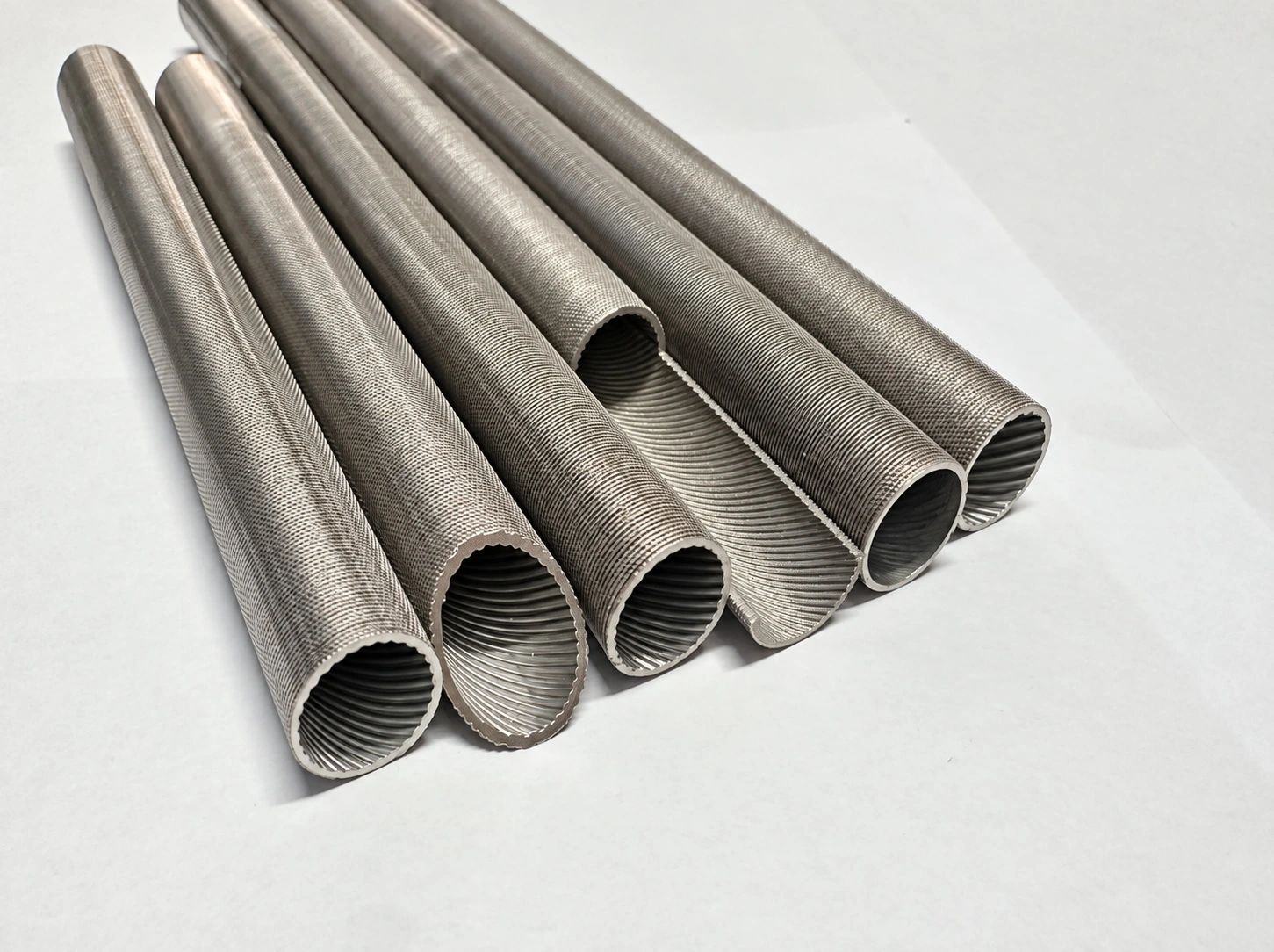
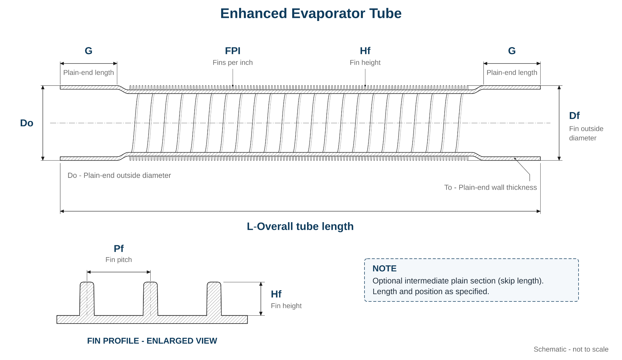
Evaporator-oriented external fin geometry may include internal enhancement. For externally finned tubes with defined internal ribs, see double enhanced heat transfer tubes. Boiling-side performance cannot be inferred from surface area alone.
View Evaporator Applications →Compare an idealized tube profile with the appropriate smooth-tube reference using the Enhanced Tube Surface Area Calculator. Use actual finished geometry; missing fin or groove widths should not be guessed. Internal and external surfaces are reported separately. Surface-area ratio is not a heat-transfer performance rating.
Confirm which fluid side controls performance, the mechanism expected from the selected profile and whether the pressure drop, fouling, cleaning and manufacturing constraints are acceptable. Compare the six profile families before selecting material or requesting a geometry-based quotation.
Inner grooved tubes mainly work on the internal surface. Low fin tubes mainly increase the external surface area. The correct choice depends on which side creates the main thermal resistance in the equipment.
Material and geometry should be reviewed according to refrigerant, cooling water, seawater, chloride-rich water, brine, oil, chemical medium, viscosity, flow regime and fouling factor.
Stainless steel and titanium are the main supply directions. Copper or copper alloy enhanced tubes can be reviewed when drawings and working conditions support copper material.
Enhanced tubes may improve local heat transfer in selected conditions, but groove or fin geometry can increase fluid friction and affect pressure drop, flow behavior, pump duty and fouling risk.
Enhanced structures may be less suitable when severe fouling, abrasive solids, frequent mechanical cleaning or strict cleanability is more important than heat transfer area.
For replacement projects, original drawing, failure mode, heat transfer target, fouling history, tube sheet design and approval process should be reviewed before changing tube type or material. See Copper Tube Replacement Review and Tube Inquiry Checklist for quotation preparation.
Inner grooved tubes and low fin tubes are both enhanced heat transfer tubes, but they solve different heat transfer problems. The selection should start from the controlling thermal resistance side, not only from the tube name.
| Tube Type | Thermal Enhancement Mechanism | Flow Geometry | Typical Review Direction | Key RFQ Information |
|---|---|---|---|---|
| Inner Grooved Tube | Internal grooves induce turbulence, secondary flow and boundary-layer disruption on the tube side. | Three-dimensional internal groove profile defined by groove depth, groove angle, helix angle and groove count. | Tube-side or refrigerant-side enhancement in evaporators, DX systems, chillers, selected condensers and coil applications. | Tube OD, wall thickness, groove depth, groove angle, helix angle, groove count, material, refrigerant or medium and drawing. |
| Low Fin Tube | External low fins increase outside surface area and can support shell-side or condensation-side heat transfer. | External fin geometry defined by OD over fins, root diameter, fin height, fin pitch, fin density and plain end length. | Shell and tube heat exchangers, condensers, oil coolers, selected evaporators and external-side heat transfer review. | Tube OD, base wall thickness, OD over fins, root diameter, fin / groove depth, fin pitch, fin density, plain end length and drawing. |
| Smooth Tube | No engineered surface enhancement; relies on base tube geometry and equipment-side design. | Plain internal and external surface. | Applications where cleanability, fouling control, simple design, mechanical cleaning or pressure drop limitation is more important. | Material grade, OD, wall thickness, length, standard, tolerance, inspection and packing requirement. If tube route is unclear, review Seamless vs Welded Tubes. |
| Project-Specific High Performance Tube | Depends on drawing, sample or thermal design target. | Custom geometry according to buyer drawing or feasibility review. | Replacement tube bundles, compact heat exchangers, copper replacement projects or equipment redesign. | Complete drawing, sample photos, material, dimensions, working condition, target performance and end-user approval requirement. |
GAOFA TECH mainly supplies stainless steel and titanium enhanced heat transfer tubes. Copper enhanced tube options can also be reviewed when customer drawings, working medium and project specification support copper material.
| Material Direction | When to Review | Typical Tube Types | Selection Notes |
|---|---|---|---|
| Stainless Steel Enhanced Tubes | Industrial cooling, condensers, evaporators, refrigeration, selected corrosion conditions and copper replacement review. | Stainless steel inner grooved tubes, stainless steel low fin tubes, stainless steel coiled tubes by application. | Review grade, medium, chloride level, heat transfer design, pressure drop, cleaning method and fabrication process. See applicable standards. |
| Titanium Enhanced Tubes | Seawater cooling, marine condensers, chloride-rich water, brine, corrosive cooling water and selected chemical heat exchanger applications. | Titanium inner grooved tubes, titanium low fin tubes, titanium enhanced heat transfer tubes by drawing. | Review grade, corrosion condition, tube sheet material, galvanic corrosion, crevice condition, temperature and customer specification. |
| Copper / Copper Alloy Enhanced Tubes | HVAC, refrigeration, clean water and traditional heat transfer designs where copper material is suitable. | Copper inner grooved tubes or copper low fin tubes by drawing and project review. | Review corrosion, erosion, ammonia compatibility, contamination requirement, copper price pressure and replacement approval. |
| Nickel Alloy / Other Alloy Enhanced Tubes | Severe corrosion, high-temperature or special process conditions where stainless steel, titanium or copper may not be suitable. | Project-specific enhanced tube by drawing and feasibility review. | Not a default supply direction. Feasibility, material availability, production route, cost and inspection scope should be confirmed first. |
There is no single ASTM standard automatically covering every enhanced geometry, base-tube route, alloy and diameter. The relevant specification depends on the material, manufacturing method, dimensional scope and intended service.
Reference for specified seamless and welded ferritic, austenitic and duplex steel condenser / heat exchanger tubes with cold-formed integral enhancement on the inner surface, outer surface or both.
Important size limit: the standard covers unfinned-end OD up to and including 25.4 mm. Larger or other custom profiles need a separately agreed specification and drawing.
Reference for specified seamless or welded titanium and titanium alloy tubes used in condensers, evaporators and heat exchangers. Enhanced fin, corrugation or rib details are defined separately by the finished-tube drawing.
Reference for specified seamless copper and copper-alloy condenser / heat exchanger tubes with cold-formed integral enhanced surfaces, internally, externally or on both sides.
A separate reference for specified welded copper / copper-alloy condenser and heat exchanger tubes with textured surfaces. It should not be treated as a universal specification for every copper fin pattern or tube route.
Enhanced tubes are reviewed when heat transfer performance, material selection and equipment reliability must be evaluated together.
Enhanced tubes can be reviewed for heat exchangers and shell and tube heat exchangers where heat transfer surface area or tube-side enhancement is required.
Inner grooved or low fin enhanced tubes may be reviewed for condenser applications according to medium, flow condition and heat transfer side.
Enhanced tubes can be reviewed for evaporator and refrigeration equipment where internal or external heat transfer enhancement is required.
Inner grooved tubes are often reviewed for industrial refrigeration heat transfer requirements, while material selection depends on the working medium.
Stainless steel or titanium enhanced tubes can be reviewed for industrial cooling and data center cooling where heat transfer performance, service life and corrosion resistance must be reviewed together.
Titanium enhanced tubes can be reviewed for seawater cooling, marine condensers, brine and chloride-rich cooling water applications.
Stainless steel or titanium enhanced tubes may be reviewed in copper tube replacement projects when copper tubes face corrosion, price pressure, contamination or compatibility concerns.
Enhanced tubes can be reviewed for selected chemical and corrosive equipment cooling systems according to medium, pH, temperature and corrosion mechanism.
Enhanced tube replacement should review original tube drawing, material, failure mode, heat transfer target, welded or seamless tube route and end-user approval requirement.
Enhanced tubes are useful in many heat transfer systems, but they should not be selected automatically. In some projects, a smooth tube, different material, different tube layout or equipment redesign may be more suitable.
Buyers should especially review pressure drop, fouling tendency, cleaning method, fluid side, corrosion condition, heat transfer target and cost before changing from smooth tube to enhanced tube.
Enhanced tube quotation depends on both base tube specification and enhanced geometry. Please provide drawings whenever possible.
| Specification Item | Information Needed | Why It Matters |
|---|---|---|
| Tube Type | Corrugated, spiral corrugated, inner grooved, low fin, enhanced condenser, enhanced evaporator, smooth replacement or unsure. | Defines the intended geometry and which heat transfer side is to be enhanced. |
| Material Grade | Stainless steel, titanium, copper / copper alloy or other material by project review. | Material affects corrosion resistance, strength, forming feasibility, cost and inspection requirement. |
| Tube OD and Wall Thickness | Tube OD, base wall thickness or wall thickness before enhancement. | Base tube size affects geometry, pressure review, tube sheet design and replacement compatibility. |
| Inner Groove Geometry | Groove depth, groove angle, helix angle, groove count, internal profile and drawing. | Required for inner grooved tube review and refrigeration-side heat transfer design. |
| Low Fin Geometry | Outer diameter over fins, root diameter, fin / groove depth, fin pitch, fin density and plain end length. | Required for low fin tube review, tube bundle layout and heat transfer surface area calculation. |
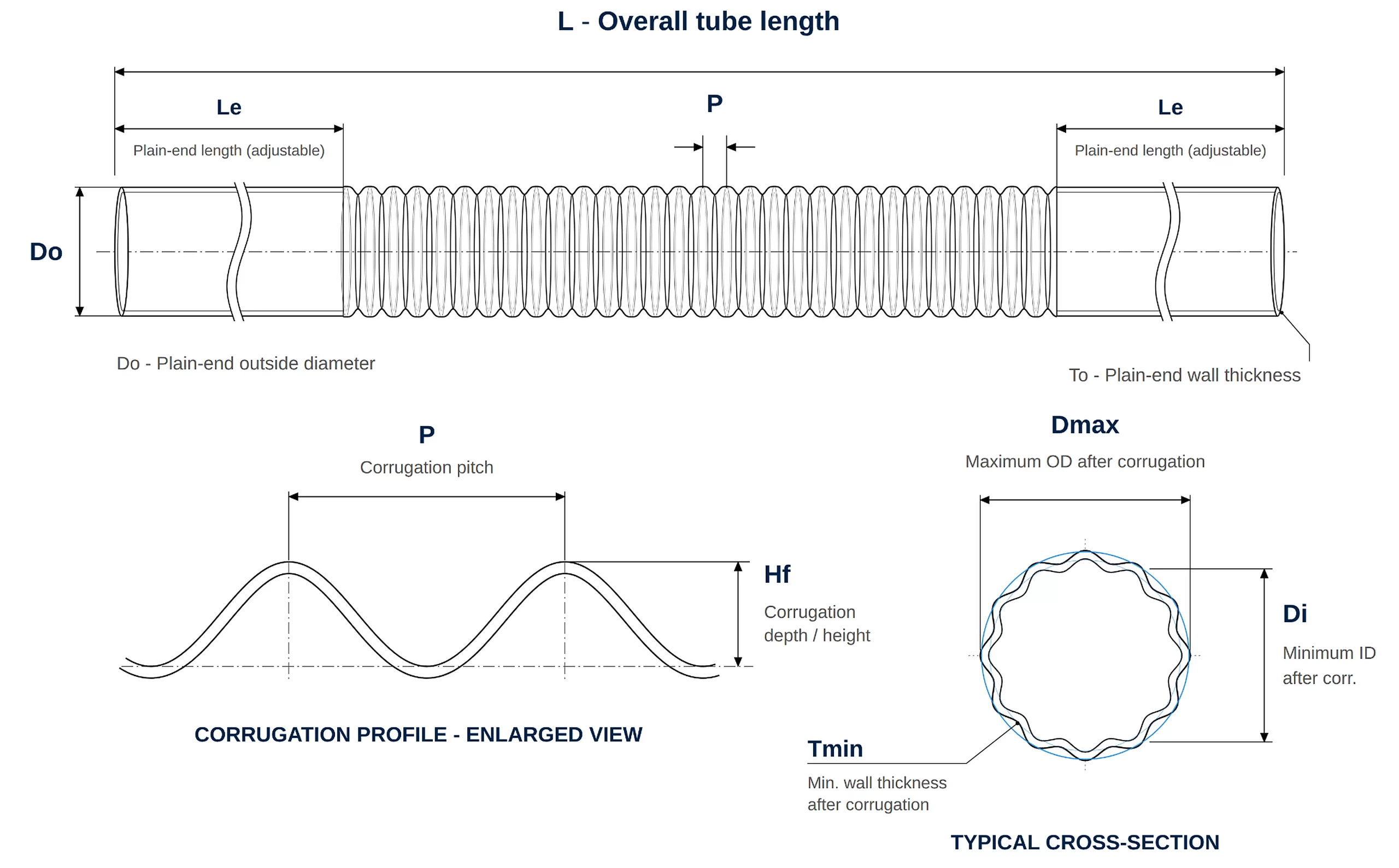
| Corrugated / Spiral Profile | Plain-end and formed-section diameters, pitch, depth, number of spiral starts, wall condition and profile drawing. | Needed to interpret the formed geometry and its relationship to the plain-tube reference; confirm pitch and wall-thickness definitions. |
| Combined Enhanced Profile | External fin geometry, internal rib geometry where applicable, smooth lands, total skipped fin length and remaining wall. | Both sides must be specified independently; internal and external surface areas are not additive thermal duty. |
| Tube Length or Coil Length | Straight length, cut length, coil length, plain end length and quantity. | Affects production planning, packing, transportation and installation. |
| Application and Medium | Condenser, evaporator, heat exchanger, refrigeration, seawater cooling, industrial cooling or replacement project. | Application determines tube type, material, corrosion review and testing scope. |
| Operating Conditions | Working medium, temperature, pressure, flow condition, pressure drop limitation, fouling and cleaning method. | Needed to judge whether enhanced tube geometry is suitable for the system. |
| Inspection Requirement | Dimensional inspection, visual inspection, PMI, eddy current, pneumatic, hydrostatic or other tests. | Testing scope affects production route, lead time and quotation. |
| Drawing or Sample | Original tube drawing, enhanced geometry drawing, sample photos or existing tube sample. | Strongly recommended for both new design and replacement tube projects. |
Enhanced tube inspection should review base tube quality, enhanced geometry, surface condition, dimensional consistency, tube end condition and packing protection.
| Inspection Item | Purpose | Buyer Notes |
|---|---|---|
| Material Verification | Confirm material grade, heat number, chemical composition and traceability. | MTC, PMI and material documents can be reviewed according to order requirement. |
| Applicable Standard & Drawing | Confirm whether the ordered standard covers the base tube, finished integral enhancement or a customer-specific geometry. | State the standard / edition, relevant size limits, remaining wall, rib or fin tolerances and agreed test / document requirements. Review standard references. |
| Base Tube Inspection | Review OD, wall thickness, straightness, surface and tube integrity before enhancement. | Base tube condition affects final groove or fin quality. |
| Enhanced Geometry Inspection | Check internal groove geometry or external low fin geometry according to drawing. | Critical for heat transfer area, flow behavior, assembly and performance review. |
| Plain End Inspection | Check tube end condition, plain end length and transition between enhanced and plain area. | Important for tube sheet connection, expansion, welding, rolling or sealing. |
| Visual Inspection | Review surface condition, scratches, dents, fin damage, groove damage and handling marks. | Enhanced structures need careful handling and packing. |
| NDT / Tightness Testing | Review tube integrity according to standard or agreed requirement. | Eddy current, pneumatic, hydrostatic or other testing should be confirmed before production. |
| Packing Review | Protect tube surface, grooves, fins, plain ends and bundle condition during shipment. | Wooden case, separators, bundle protection and packing photos can be discussed before shipment. |
Review GAOFA TECH’s tube inspection examples, including PMI checking, OD inspection, wall thickness inspection, visual inspection, eddy current testing, pneumatic testing, ultrasonic testing and packing review.
For an initial enquiry, material, profile, size and quantity are enough to begin a technical review. A final enhanced-tube quotation also depends on the finished fin or groove drawing, plain ends, application and inspection requirements.
For replacement projects, original drawings, current tube samples, failure mode and required performance target are especially important.
Copy this short template and send us the basic tube requirement.
Material review note: If you are not sure which material grade, tube form or enhanced geometry is suitable, please tell us the actual application, working medium, operating temperature, pressure, fouling / cleaning concern, corrosion or scaling concern, heat transfer target and any previous failure issue if available.
Please send tube type, material grade, OD, wall thickness, groove or fin geometry, length, quantity, working medium, temperature, pressure, heat transfer requirement, pressure drop limitation, fouling condition, cleaning method and application details. If you are not sure whether to choose inner grooved tube or low fin tube, please send the application and current tube drawing first.
Enhanced heat transfer tubes are tubes with internal grooves, external fins or other engineered surface profiles used to improve heat transfer in selected heat exchanger, condenser, evaporator and refrigeration systems. Their purpose is to reduce the controlling thermal resistance in the system, not simply to create a special tube appearance.
In many heat transfer systems, part of the resistance comes from the fluid boundary layer near the tube wall. Inner grooved tubes can induce turbulence, secondary flow and boundary-layer disruption on the tube side. Low fin tubes increase outside surface area and can reduce external-side or condensation-side resistance. The actual benefit depends on thermal resistance distribution, fluid properties, flow regime, fouling factor, pressure drop and equipment design.
GAOFA TECH reviews six surface-profile families: corrugated, spiral corrugated, inner grooved, low fin, enhanced condenser and enhanced evaporator tubes. Stainless steel and titanium are important material directions, but the feasibility of each combination depends on the geometry and production route.
| Tube Direction | Material Families | Related Product Pages |
|---|---|---|
| Inner grooved tubes | Stainless steel, titanium and project-specific material review | Inner Grooved Tube, Titanium Inner Grooved Tube |
| Low fin tubes | Stainless steel, titanium and copper / copper alloy by drawing review | Low Fin Tube, Stainless Steel Low Fin Tube, Titanium Low Fin Tube |
| Corrugated / spiral corrugated | Material and finished-wall geometry by project review | Corrugated Tube; Spiral profile drawing review |
| Enhanced condenser / evaporator | Combined or tailored geometries subject to drawing review | Condenser & Evaporator Applications |
Inner grooved tubes and low fin tubes solve different heat transfer problems. The difference is not only the tube appearance, but also the enhancement side, flow geometry and main thermal resistance target.
| Item | Inner Grooved Tube | Low Fin Tube |
|---|---|---|
| Main enhancement side | Internal tube side or refrigerant side | External shell side or outside surface |
| Mechanism | Induced turbulence, secondary flow and boundary-layer disruption | Extended surface area, thinner external film resistance and improved shell-side area density |
| Geometry | Groove depth, groove angle, helix angle and groove count | OD over fins, root diameter, fin height, fin pitch and plain ends |
| Typical review direction | Tube-side evaporation, refrigeration, DX evaporators, chillers and selected condensers | Shell-side condensation, oil coolers, compact heat exchangers and selected condenser / evaporator designs |
Thermal engineers should start from the controlling side of heat transfer. If the main limitation is tube-side or refrigerant-side convection, inner grooved tubes may be reviewed. If the main limitation is shell-side condensation, external film resistance or outside surface area, low fin tubes may be reviewed.
Stainless steel and titanium have lower bulk thermal conductivity than copper alloys, but the final overall heat transfer coefficient is not determined by bulk conductivity alone. Thermal resistance also includes convection resistance, tube wall thickness, fouling resistance, surface geometry and operating flow velocity.
In selected applications, stainless steel or titanium enhanced tubes may help compensate for the conductivity difference through thin-wall design, higher allowable velocity in corrosion-resistant service, lower fouling or corrosion deposit risk, and enhanced surface geometry. This is especially relevant when copper faces corrosion, ammonia compatibility limits, contamination concerns or price pressure. Final replacement should still be confirmed by thermal calculation, pressure drop review, tube-sheet design and customer approval.
Titanium low fin tubes and titanium inner grooved tubes should be reviewed when a project needs both corrosion resistance and heat transfer enhancement. Typical review directions include seawater condensers, marine cooling systems, chloride-rich cooling water, brine service and selected chemical cooling applications.
Titanium is not selected only because it is an enhanced tube material. The review should include chloride level, flow velocity, suspended solids, fouling, cleaning method, crevice design, tube sheet material, galvanic contact, fluoride risk and customer specification.
No. Enhanced tubes are useful when the enhanced surface actually reduces the controlling thermal resistance and the system can accept the pressure drop, fouling and fabrication implications. Smooth plain tubes may be more suitable when the medium is dirty, scaling is severe, abrasive particles are present, mechanical cleaning is frequent, or pressure drop and simple maintenance are more important than surface enhancement.
For replacement projects, the original tube bundle design, failure mode, cleaning method and performance target should be reviewed before changing from smooth tubes to enhanced tubes.
Yes. Enhanced profiles can increase fluid friction and may create higher local pressure drop, especially for inner grooved tubes or designs that intentionally disturb flow. This should be discussed honestly before quotation or equipment redesign.
The engineering question is whether the complete system is optimized. If enhanced tubes increase heat transfer enough under the actual flow condition, the equipment may require fewer tubes, a smaller shell, fewer tube passes or a different flow arrangement. In an overall system calculation, the final pressure drop may be acceptable, similar or sometimes lower than the original design, but this cannot be assumed without geometry, medium, flow rate and thermal calculation.
Enhanced tubes, especially low fin tubes, normally require plain ends or land sections for tube-sheet expansion, welding, rolling, sealing or mechanical assembly. The plain end length should follow the drawing, tube sheet thickness, expansion length, welding method and support plate layout.
For low fin tubes, OD over fins, root diameter, plain end OD, transition area and land length must be controlled according to the customer drawing. In many designs, plain sections are configured to support tube insertion, tube-sheet fit and reliable sealing while avoiding fin damage during assembly. If support plates require smooth sections between finned areas, those land sections should be marked clearly on the drawing.
Enhanced tube quotation depends on both the base tube and the enhanced geometry. Buyers should provide drawings whenever possible, especially for replacement tube bundles or OEM equipment.
Enhanced tube inspection should cover the base tube, the enhanced profile and the assembly-related areas. Important items include material verification, OD and wall thickness inspection, groove or fin geometry inspection, plain end length inspection, transition area review, surface condition, tube end condition, NDT or tightness testing when required, and packing protection.
For more details, buyers can review GAOFA TECH’s Quality Control page. Enhanced tubes need careful handling because fins, grooves and land sections can be damaged if packing and transportation are not reviewed properly.
Yes. Enhanced tubes may be reviewed for selected data center cooling or liquid cooling support equipment when the design requires compact heat transfer, corrosion-resistant materials or improved thermal performance. The review should include coolant type, water chemistry, temperature, pressure, flow rate, pressure drop limitation, fouling risk, cleaning method and equipment design.
For suitable stainless steel integral enhanced condenser and heat exchanger tubes, ASTM A1012 may apply within its unfinned-end OD limit of 25.4 mm. ASTM B338 is a titanium heat exchanger base-tube reference; ASTM B359/B359M addresses specified seamless copper and copper-alloy integrally enhanced tubes. Welded copper tubes with textured surfaces may fall under ASTM B1014 where applicable. The agreed finished drawing, material route, dimensions and inspection requirements control the actual order. See the standards comparison.
For a first quotation, please provide material grade, tube form, OD × wall thickness × length and quantity. For enhanced tube geometry, drawings are strongly recommended because inner groove depth, helix angle, fin height, fin pitch, plain end length and tube-sheet connection can affect feasibility, price and inspection.
A useful enhanced tube RFQ should include tube type, material grade, OD, wall thickness, groove or fin geometry, length, quantity, application, working medium, temperature, pressure, flow condition, heat transfer target, pressure drop limitation, fouling factor, cleaning method, tube-sheet material, connection method, inspection requirement, packing requirement and destination.
For copper replacement, seawater cooling, refrigeration or replacement tube bundle projects, please also provide the original drawing, existing material, failure mode, operating history and target improvement. You can also start from the Tube Inquiry Checklist or send drawings through the contact page.