Opens in a new tab
Metal Tubes for Heating Elements, Heat Exchangers, Cooling and Corrosive Applications
GAOFA TECH GF GAOFA TECH Industrial Tubes
Home
Products
Applications
Resources
About Us Contact Us Request a Quote
GAOFA TECH / Engineering Tools

Enhanced Tube Surface Area Calculator

Explore six enhanced heat transfer tube profiles using photographs, drawings and published geometry references. Enter your tube geometry to estimate theoretical enhanced surface area and compare it with a smooth-tube reference. Selected catalogue area examples are also available. Calculations use stated simplified models and do not predict heat-transfer performance.

Corrugated TubeSpiral Corrugated TubeInner Grooved TubeLow Fin TubeEnhanced Condenser TubeEnhanced Evaporator Tube
01 / Identify your tube

Six enhanced tube families

Choose the tube profile that matches your application, then compare its photo and geometry drawing with your own specifications.

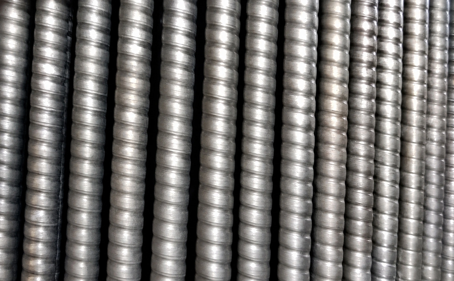
GAOFA TECH corrugated tube representative product photo showing tube surface or cutaway profile
Tube samples
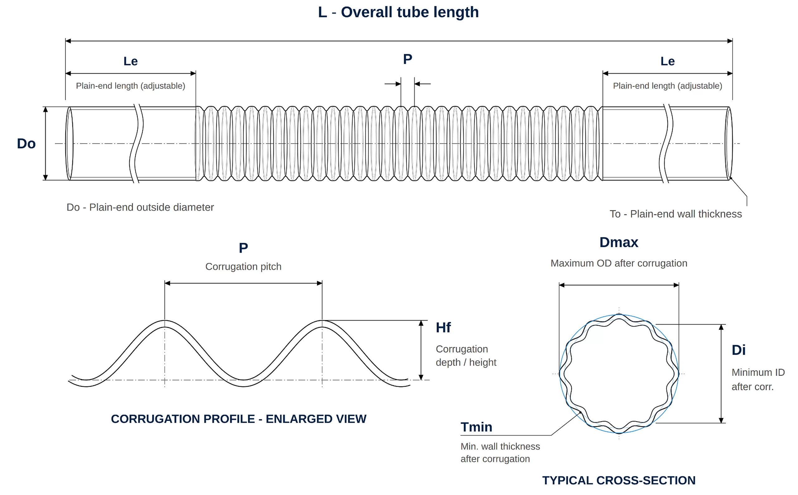
GAOFA TECH corrugated tube engineering geometry drawing
Geometry drawing
01 / 06

Corrugated Tube

Corrugated wall geometry with defined pitch and depth.
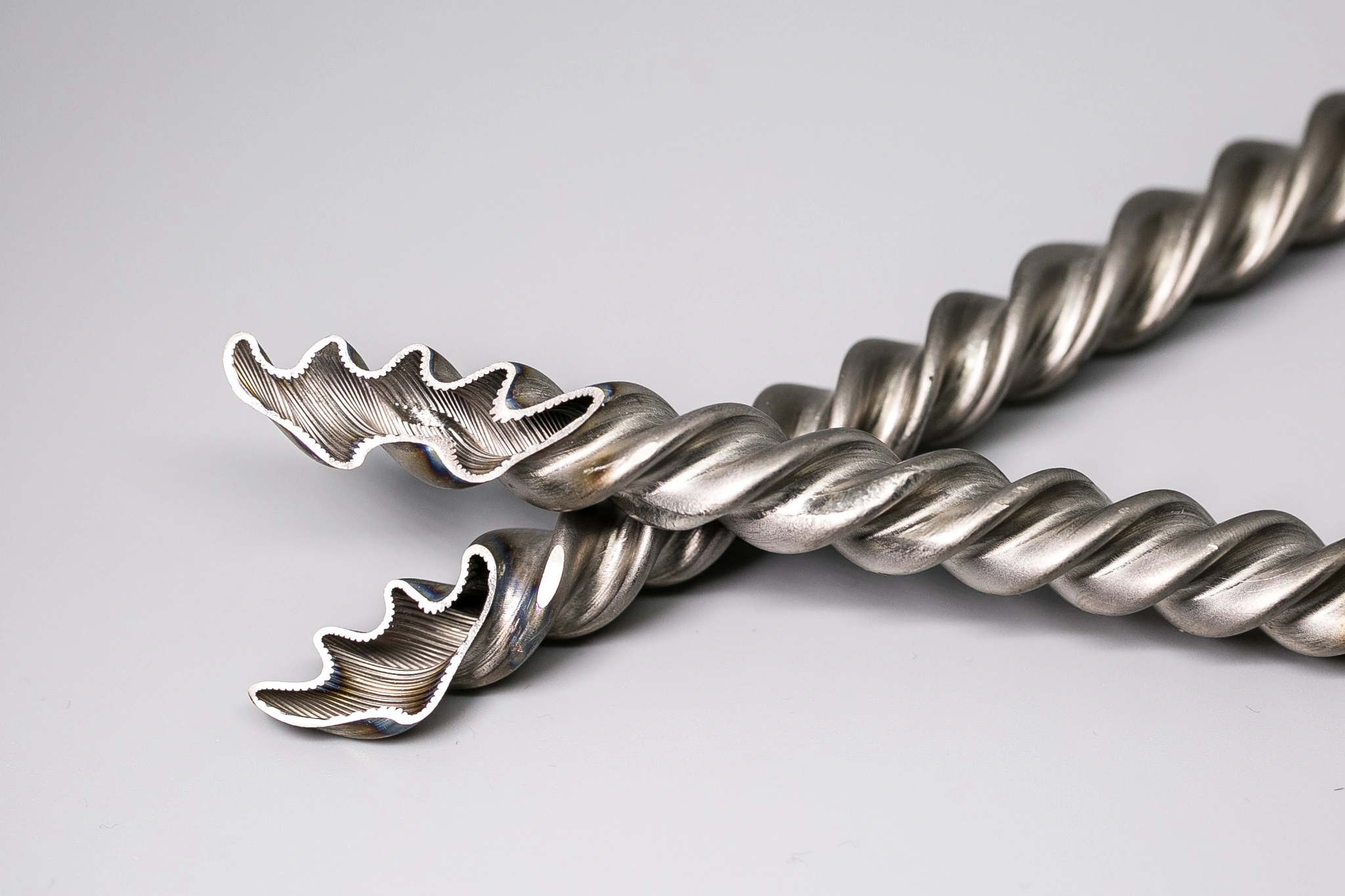
GAOFA TECH spiral corrugated tube representative product photo showing tube surface or cutaway profile
Tube samples
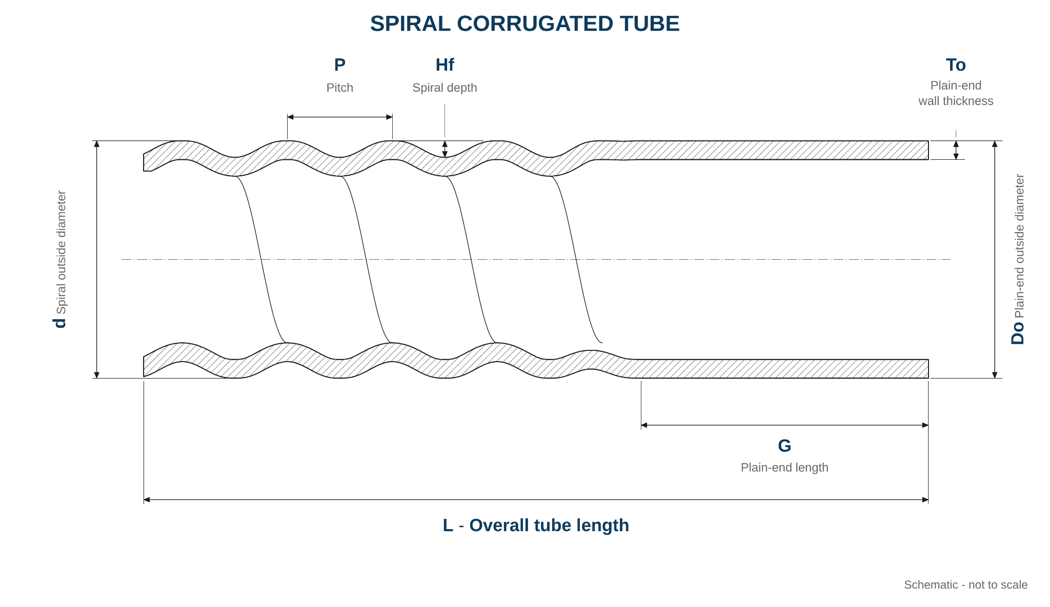
GAOFA TECH spiral corrugated tube engineering geometry drawing
Geometry drawing
02 / 06

Spiral Corrugated Tube

Multi-start spiral corrugations, with profile and starts defined by drawing.
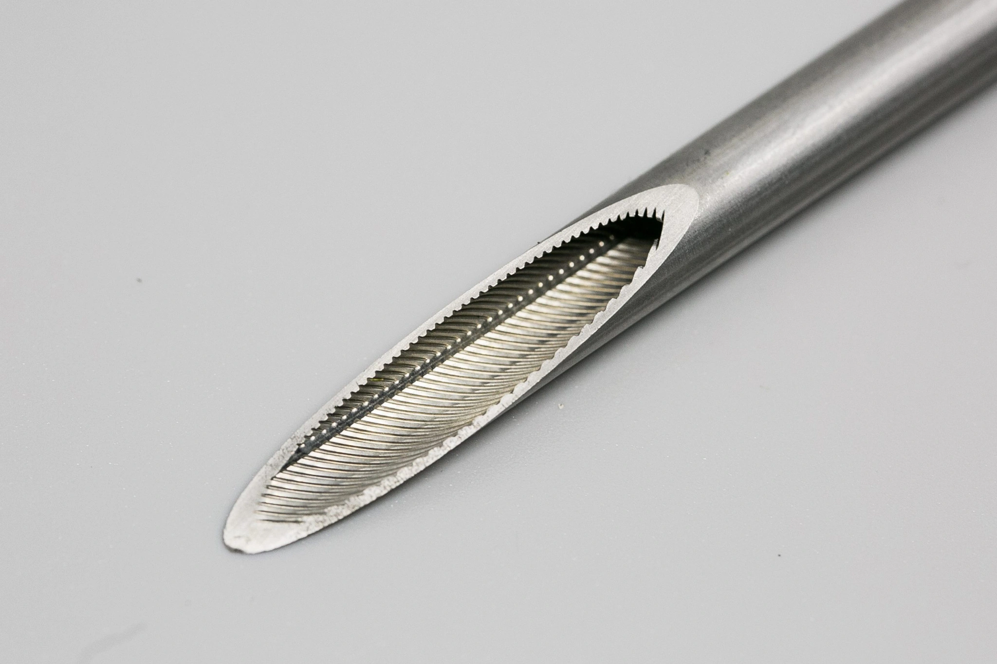
GAOFA TECH inner grooved tube representative product photo showing tube surface or cutaway profile
Tube samples
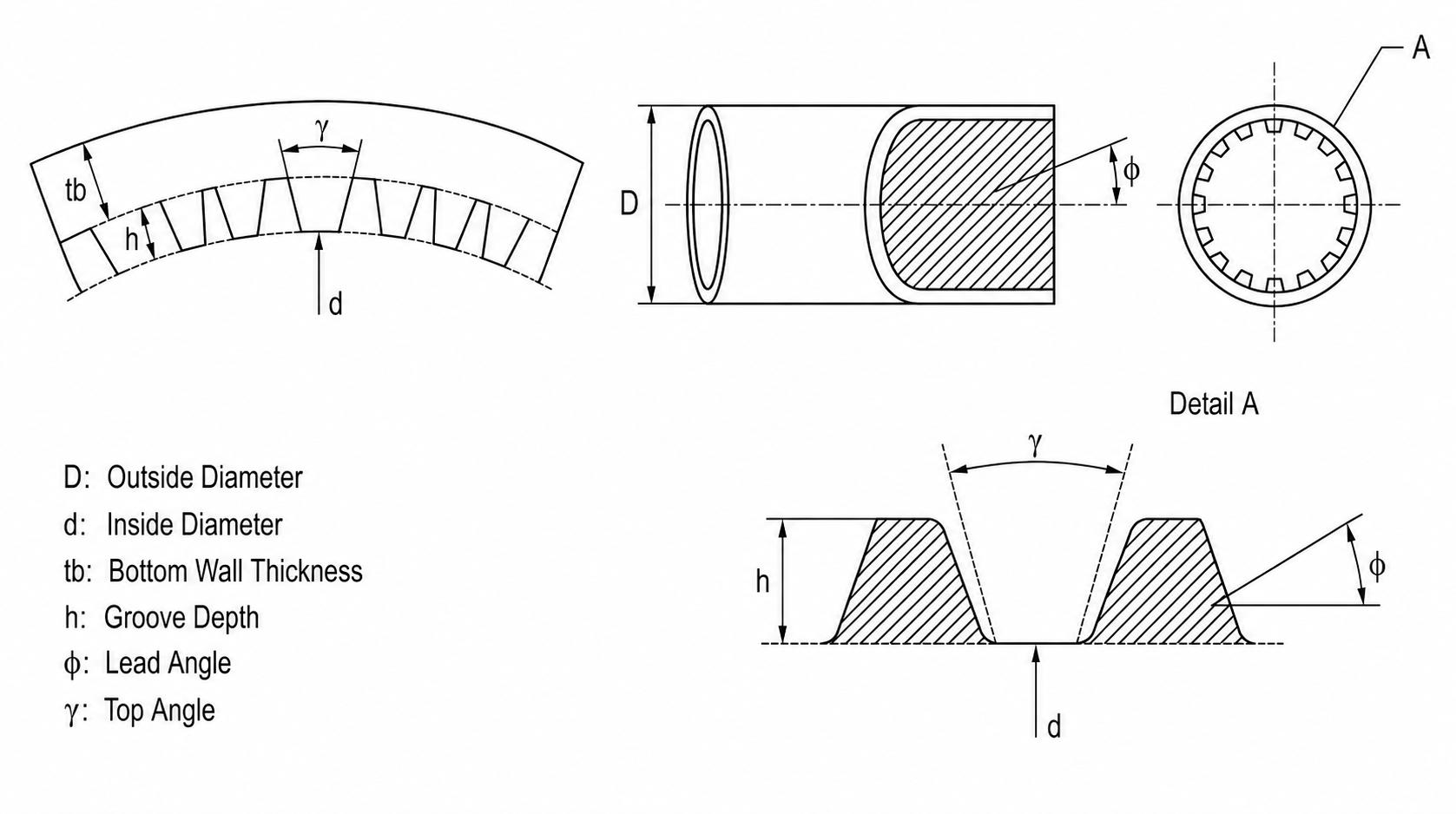
GAOFA TECH inner grooved tube engineering geometry drawing
Geometry drawing
03 / 06

Inner Grooved Tube

Helical internal grooves for tube-side surface geometry.
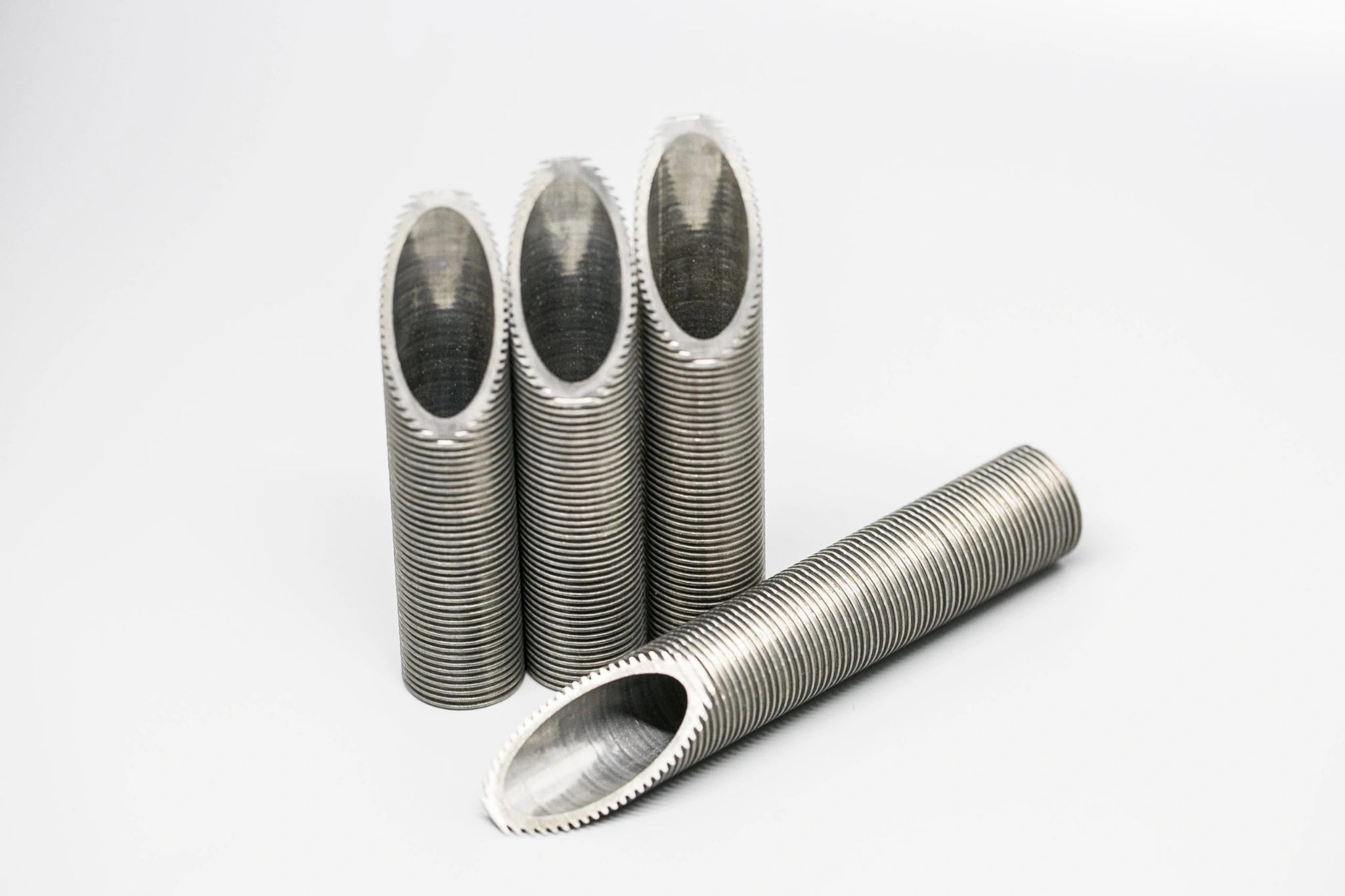
GAOFA TECH low fin tube representative product photo showing tube surface or cutaway profile
Tube samples
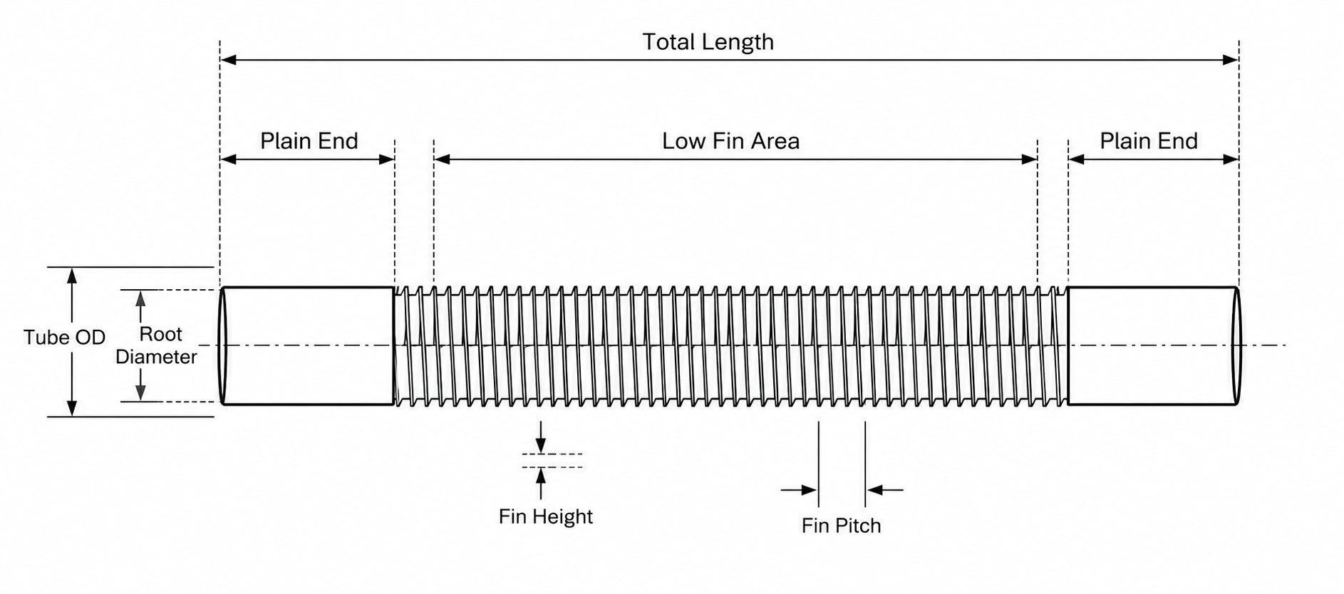
GAOFA TECH low fin tube engineering geometry drawing
Geometry drawing
04 / 06

Low Fin Tube

Integral external fins with defined fin pitch, OD and root diameter.
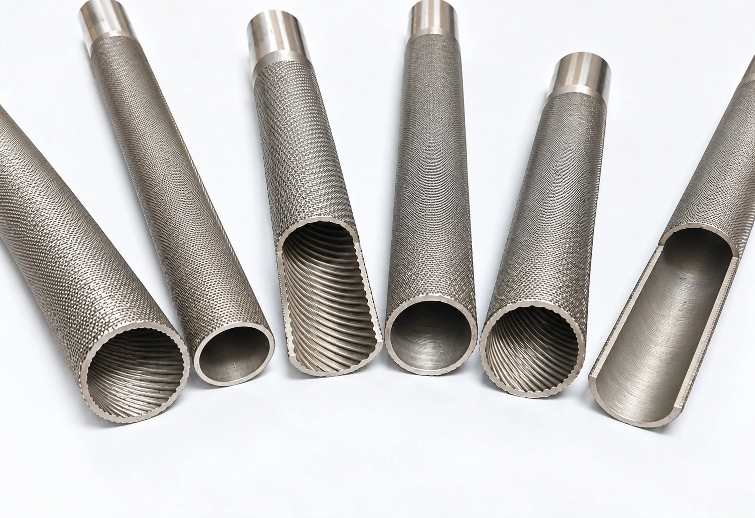
GAOFA TECH enhanced condenser tube representative product photo showing tube surface or cutaway profile
Tube samples
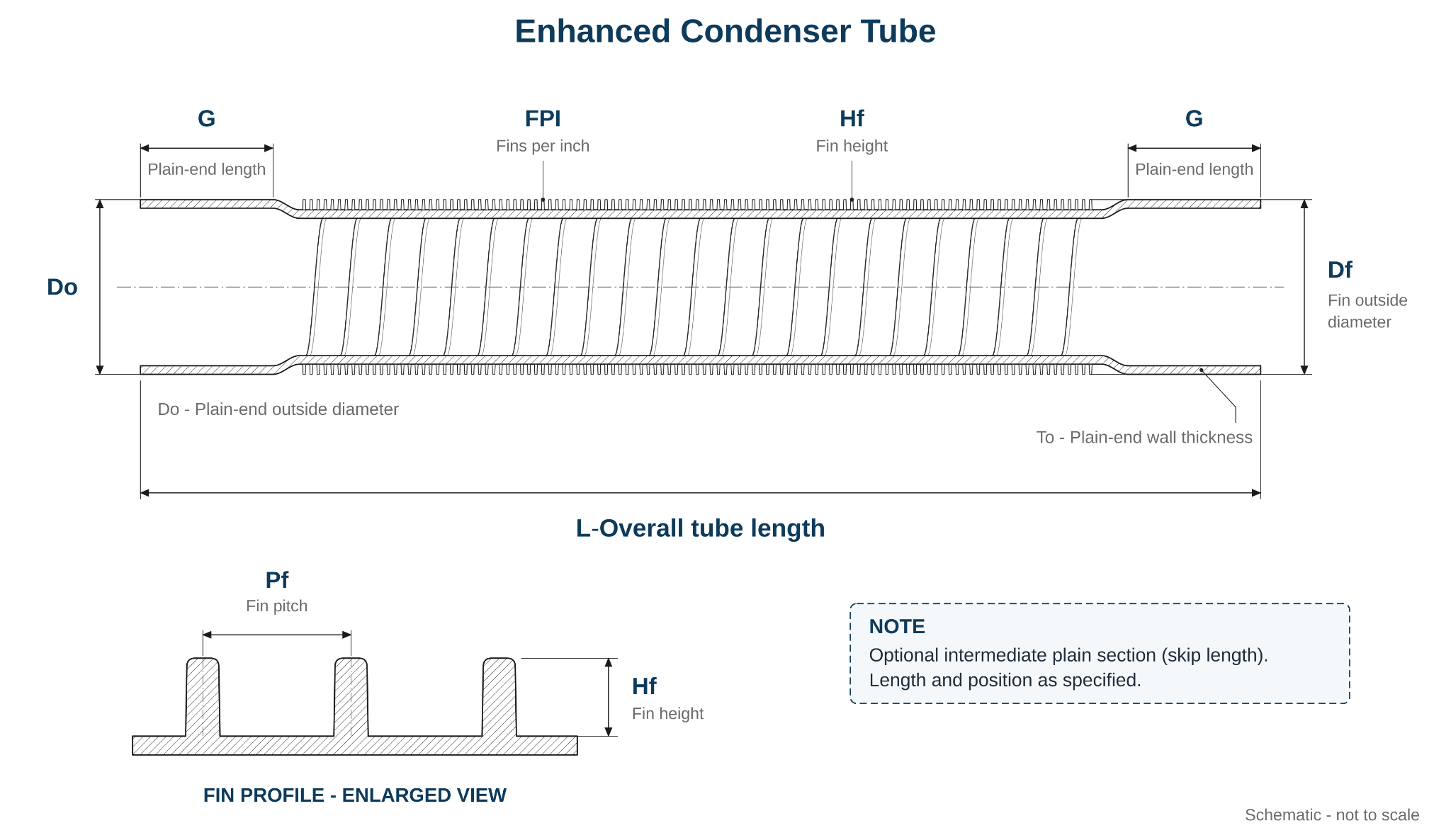
GAOFA TECH enhanced condenser tube engineering geometry drawing
Geometry drawing
05 / 06

Enhanced Condenser Tube

Structured external fins with optional internal ribs.
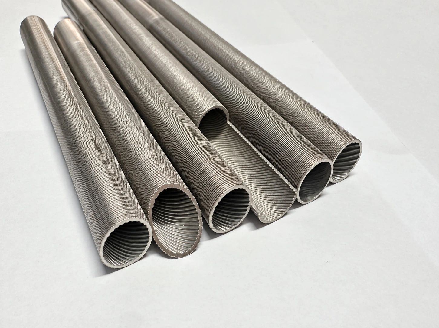
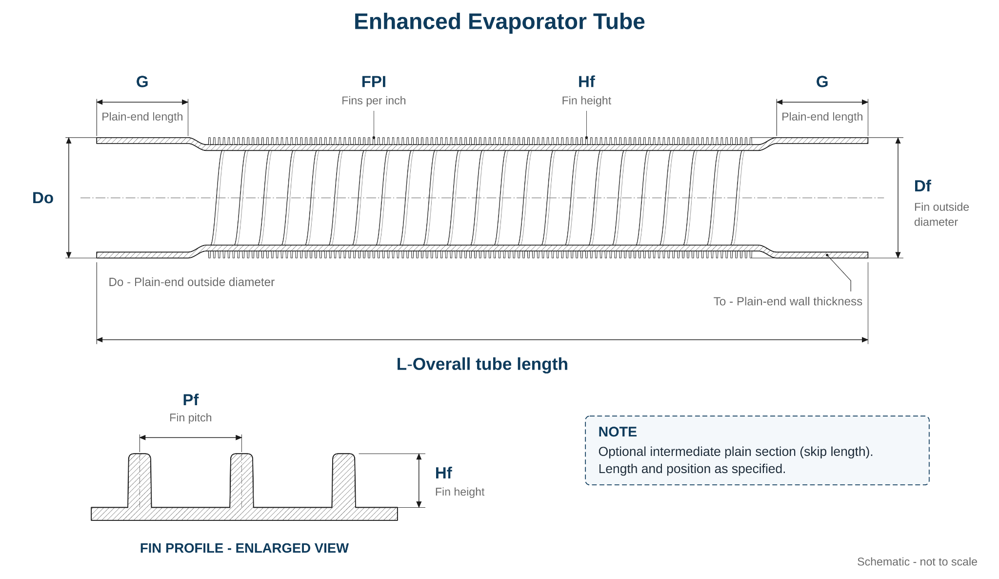
GAOFA TECH enhanced evaporator tube representative product photo showing tube surface or cutaway profile
Tube samples
GAOFA TECH enhanced evaporator tube engineering geometry drawing
Geometry drawing
06 / 06

Enhanced Evaporator Tube

Evaporator-profile fins with optional internal helical ribs.

02 / Geometry screening

Select a profile and calculate

Enter your dimensions for a theoretical geometric area estimate. Some fin and rib models need extra widths beyond the general product drawing; these are labelled in the model diagram. Catalogue examples are a separate published reference.

Corrugated Tube

Idealized enhanced area model
mm input / m² results

Start with your dimensions. Select Catalogue examples only if you want to review a published geometry reference rather than estimate from your own drawing.

Choose a catalogue example (optional)
Catalogue geometry examples, not approved manufacturing drawings or measured thermal results. Missing section dimensions must be supplied separately.

Enter geometry from your drawing

Enter drawing-labelled dimensions below. This mode estimates the enhanced geometric surface area from your dimensions and an explicitly simplified profile. Fin and rib models require the section widths shown in the supplementary diagrams. Unspecified widths are intentionally left blank; enter values from your drawing or measurement. Geometry examples are not manufacturing specifications, and calculated areas are not measured heat-transfer performance.

Tube length, ends and quantity
Enter the geometry and calculate a theoretical enhanced area. Use the supplementary fin or rib sketch where the product drawing does not label a necessary width.
-Per tube
-Per tube, source-labelled
-Not thermal performance

Results are for engineering screening only.

Internal surface (reported separately)
-
-
-
Calculation boundary: Reference values may be rounded and derived from supplier geometry data; they are not GAOFA thermal test measurements. Surface-area ratios do not establish heat-transfer improvement, pressure drop, fouling resistance or suitability for a specific condenser or evaporator. The geometric model omits local transition shapes, roundovers, knurling texture and manufacturing deformation. Simple sinusoidal corrugations and idealized annular fins or ribs are not faithful CAD reconstructions.
03 / Understand the result

What the area figure means

For engineering comparisons, the fluid side, tube geometry and area basis must be identified before comparing numbers.

Catalogue reference versus geometric model

  • Catalogue reference: uses the supplied m²/m for that exact example and applies it only to the enhanced length.
  • Idealized geometry: estimates the entered profile using an explicitly simplified sinusoidal corrugation, annular fin or helical rib model. Additional cross-section widths are required where shown.
  • Smooth baseline: uses π × smooth-reference diameter × total length, with all dimensions converted from mm.
  • Plain ends are treated as smooth surface. If zero is entered, the whole length is assumed enhanced.

Why the actual thermal result can differ

  • Heat transfer coefficients, flow regime, condensation or boiling mechanism and fouling matter.
  • Knurling, grooves, rounded tips, surface roughness and forming deformation alter actual geometry.
  • The inside and outside surfaces act on different heat transfer sides; their areas must never be added as one effective area.
  • Final calculations should use customer-approved drawings and, where required, CAD or measured surface data.

Need a drawing-based enhanced tube quotation?

Send material grade, tube profile, OD × wall × length, quantity, application and the fin / groove drawing. We can review production route, geometry, inspection and export supply requirements.

Send your tube enquiry
04 / FAQ and product navigation

Engineering calculator FAQ

Short answers to the questions that affect the credibility of a surface-area comparison.

Does a 50% increase in geometric area mean 50% more heat transfer?

No. Geometry alone does not determine overall heat-transfer duty. Coefficients, fin efficiency, phase-change behavior, pressure drop, fouling and equipment conditions must be reviewed.

What is included in the idealized enhanced area?

The calculator estimates smooth-reference and enhanced geometric area using simplified sinusoidal or straight-sided profiles. For annular fins and helical ribs, it additionally needs top and base widths marked on the supplementary model diagrams. Knurling, radii, complex formed sections and local transitions are excluded. Results are theoretical, not measured.

Are the low fin and enhanced condenser / evaporator values measured?

No. They are supplier-provided catalogue reference area values for illustrative geometry combinations. They are not GAOFA laboratory test results or proof of enhanced thermal performance.

Can I use the same calculated values for stainless steel and titanium tubes?

A purely geometric area model can apply to an identical finished geometry, but it does not establish that every material can be manufactured to that profile. Forming feasibility, tolerances and corrosion suitability must be reviewed for each material.

Can a double enhanced tube use the combined inner and outer area as one result?

No. Internal and external areas correspond to different fluid sides. The calculator never sums inner and outer areas; when internal rib geometry is supplied, it reports inner area separately with its own smooth-side reference.