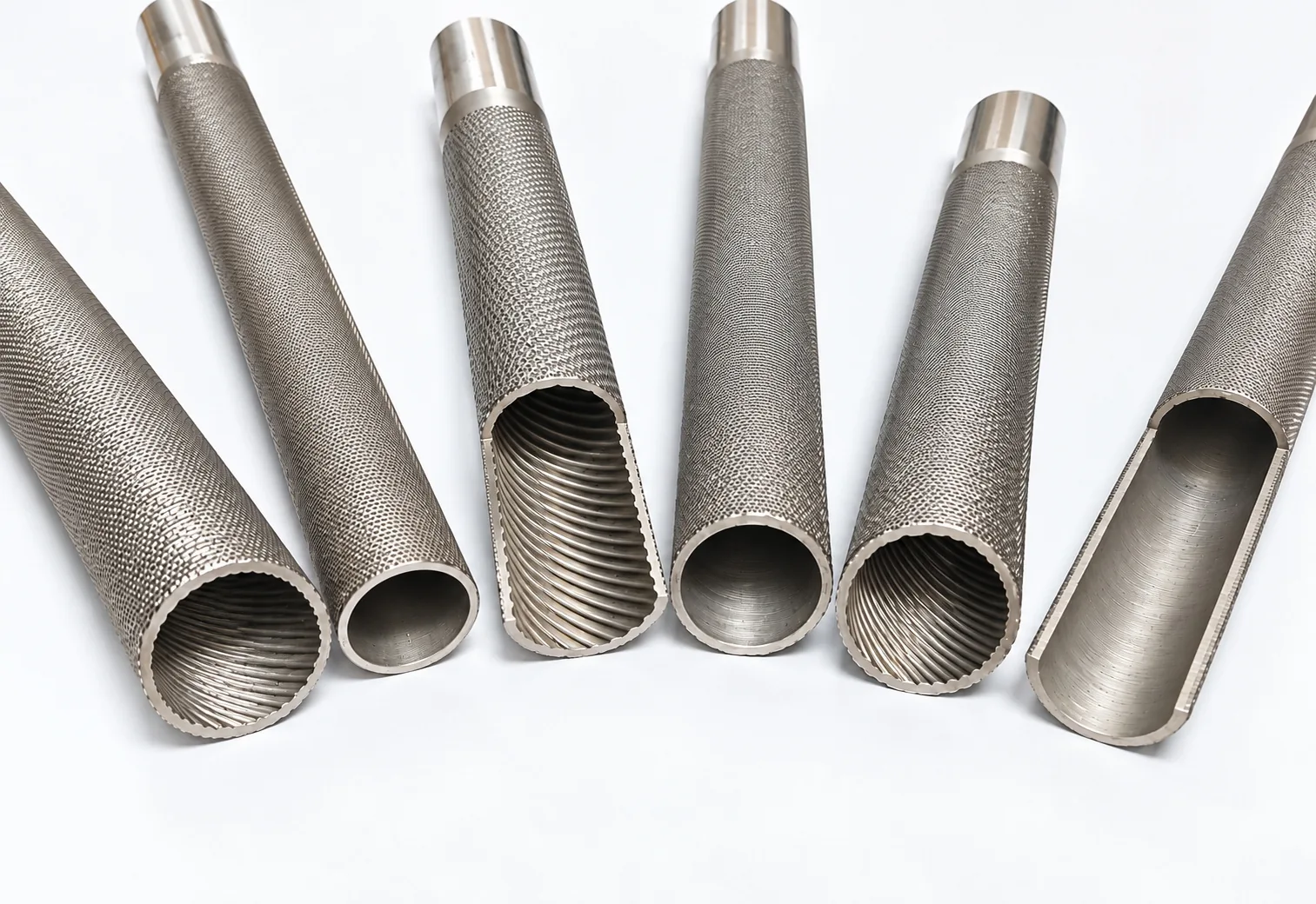
GAOFA TECH manufactures and supplies dual enhanced heat transfer tubes—also called double enhanced tubes, doubly enhanced tubes or internally and externally enhanced heat exchanger tubes—with external fins and internal helical ribs formed on the same tube for specified condenser, evaporator and shell-and-tube heat exchanger designs.
As a direct dual and double enhanced tube manufacturer and supplier, GAOFA TECH supports drawing-defined stainless steel designs (304, 304L, 316L) and titanium enhancement inquiries (Grade 1, Grade 2), with in-house forming, dimensional review and export support. Finished-tube specifications, applicable base-tube standards, inner and outer geometry and inspection requirements are confirmed against the approved drawing and purchase order.
External fin density26–50 FPIProfile-dependent range
Overall lengthUp to 15 mSubject to material and route
General catalogue review ranges, not a guarantee that every size, grade, fin profile and internal rib configuration is available in combination.
01 / Actual drawing details
Dual Enhancement: External Fins and Internal Helical Ribs
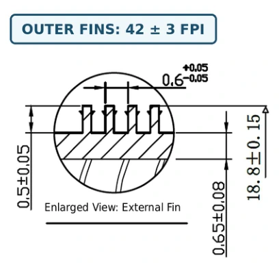
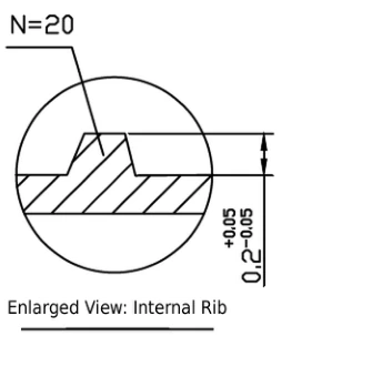
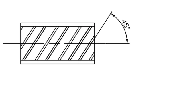
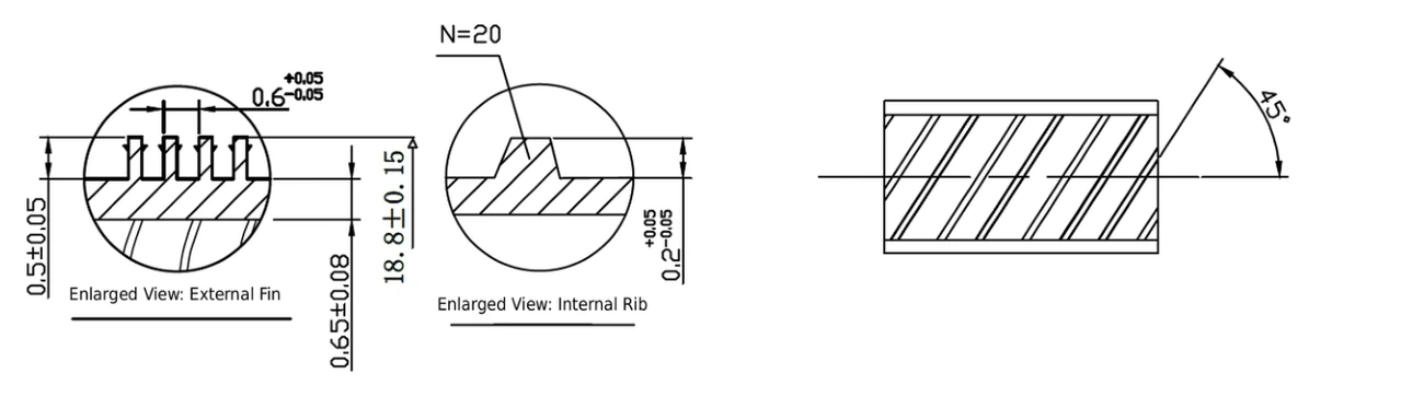
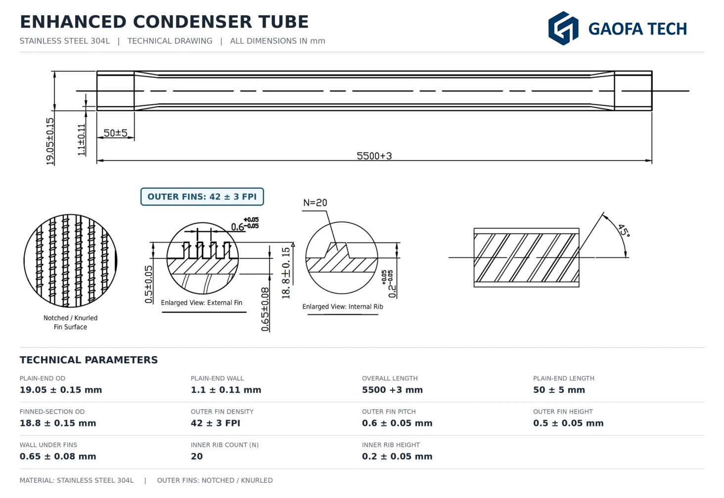
The 304L condenser drawing details below show an external fin section, an internal rib section and the helical rib direction. This is one specific drawing example—not a universal geometry.
External fins — low fin profile with notching
Source drawing detail · 42 ± 3 FPI · fin height 0.50 ± 0.05 mm
The outside surface uses integral low fins with a specified notched / knurled fin pattern. Fin height, pitch, final fin OD and wall remaining under the fins are drawing-dependent.
Notching is a surface feature on the fins; it is not the same as a separate internal groove.
The inner surface has formed helical ribs, illustrated by the original rib cross-section and helix drawing. Rib count, height, width and direction can differ between condenser and evaporator specifications.
This is a drawing example—not a universal double-enhanced profile.
Definition: A double enhanced heat transfer tube (or dual enhanced tube) combines specified external and internal enhancement on the same finished tube. Some catalogue photos also show smooth-bore examples; those are not double enhanced, even when their outer surface has fins.
02 / Product configurations
Available Dual & Double Enhanced Tube Configurations
Outer fin geometry and internal rib geometry are defined together, not selected from isolated dimensions.
01
Low Fin + Internal Ribs
External integral low fins combined with specified internal helical ribs (inner ribbed and outer finned tube). Suitable for drawing-based reviews where both shell-side and tube-side heat transfer need consideration.
02
Notched / Knurled Fins + Internal Ribs
External fins with an additional textured or notched profile, paired with internal helical ribs. Fin notching and rib geometry are reviewed against forming and operating requirements.
03
Continuous Finned Length or Skip-Fin
Fully continuous finning between required plain ends, or an intermediate plain (skip-fin) section where tube supports, baffles or TEMA-based shell-and-tube exchanger design requirements call for it.
Performance note: Surface area alone does not establish condenser or evaporator performance. The fluid side, phase-change mechanism, heat-transfer coefficient, pressure drop, fouling and mechanical design all matter.
03 / Materials
Stainless Steel and Titanium Dual / Double Enhanced Tubes
GAOFA TECH manufactures and supplies double enhanced tube designs to agreed geometry; material grade and manufacturing route are reviewed separately for each configuration.
Stainless / Stainless Steel / SS
Stainless Steel Dual & Double Enhanced Tubes
304, 304L and 316L are key stainless steel directions for dual enhanced tubes. The 304L condenser and evaporator drawings shown on this page illustrate different combinations of external fin geometry and internal helical ribs.
As a stainless steel double enhanced tube manufacturer and supplier, GAOFA TECH has in-house capabilities for complete double-sided enhancement—not only external low finning. For qualifying integrally enhanced stainless steel condenser and heat exchanger tubes, ASTM A1012 is a relevant finished-tube standard (unfinned end OD up to 25.4 mm). ASTM A213, A249 or A269 may separately apply to the starting tube, depending on its production route. Final dimensions, surface geometry and inspection requirements are confirmed against the approved drawing.
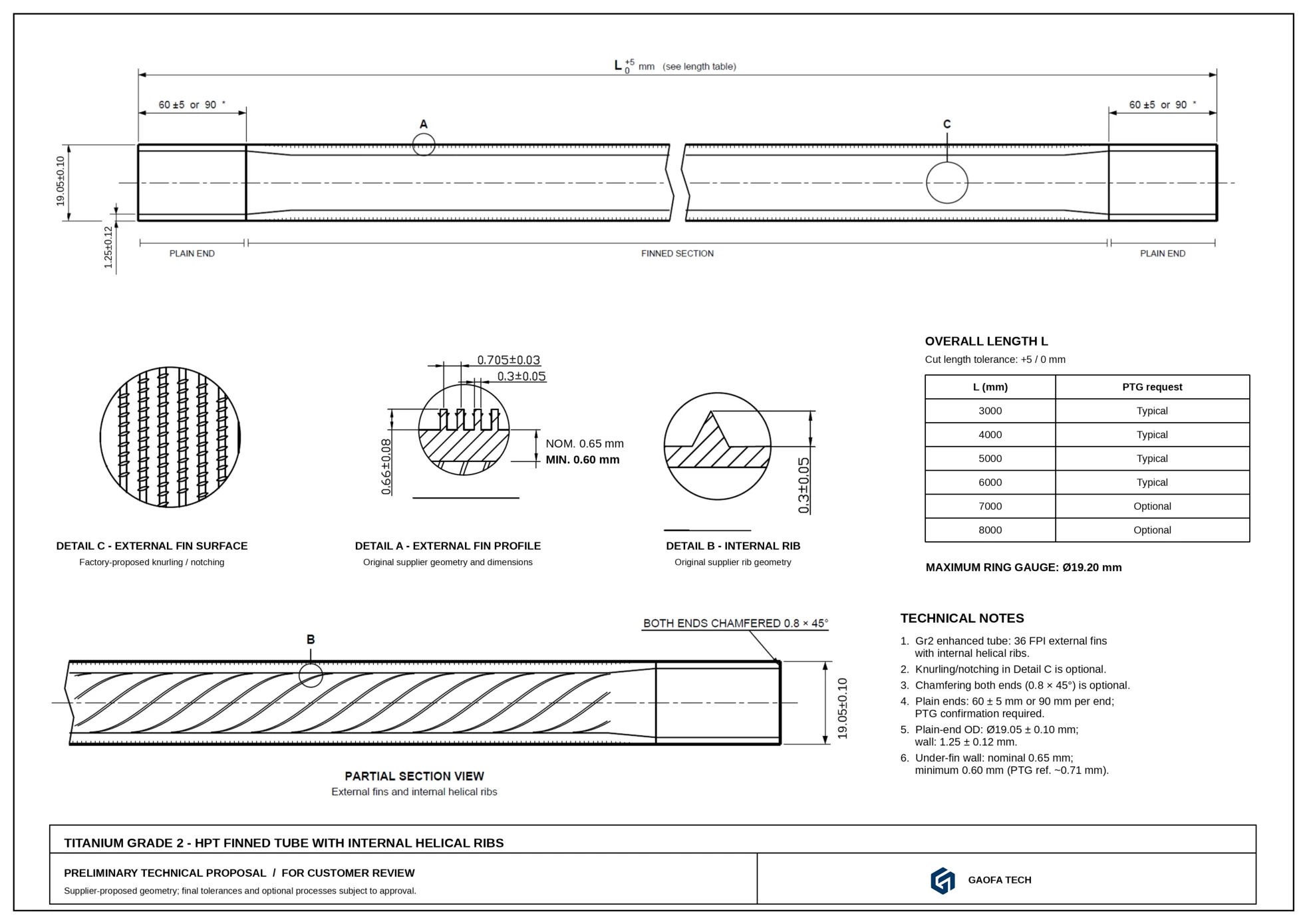
As a project-based titanium double enhanced tube supplier and manufacturer, GAOFA TECH reviews Titanium Grade 1 and Grade 2 dual enhanced tubes for specified heat exchanger requirements. The titanium drawing provided is a proposed geometry reference; its final manufacturability and tolerances must be confirmed before quotation.
Titanium applications may include suitable seawater, brine and chloride-rich cooling systems. ASTM B338 may govern the titanium seamless or welded base tube where specified; the additional fin-and-rib geometry is controlled by the drawing and agreed requirements. Corrosion conditions, pressure, forming route and equipment design still require review. No assumption is made that every stainless steel geometry is directly transferable to titanium.
Copper / copper alloy integral-fin reference: For suitable seamless copper or copper-alloy condenser and heat exchanger tubes with cold-formed integral external fins, internal enhancement, or both, ASTM B359/B359M is the relevant product standard to review. Copper material, geometry and manufacturing availability are considered by drawing and project; this does not imply that every copper alloy or enhancement profile is offered.
04 / Applications
Dual Enhanced Condenser Tubes & Evaporator Tubes
Condenser and evaporator enhanced tubes can use both stainless steel (SS) and titanium, but each application requires its own geometry, working-fluid and pressure-drop review.
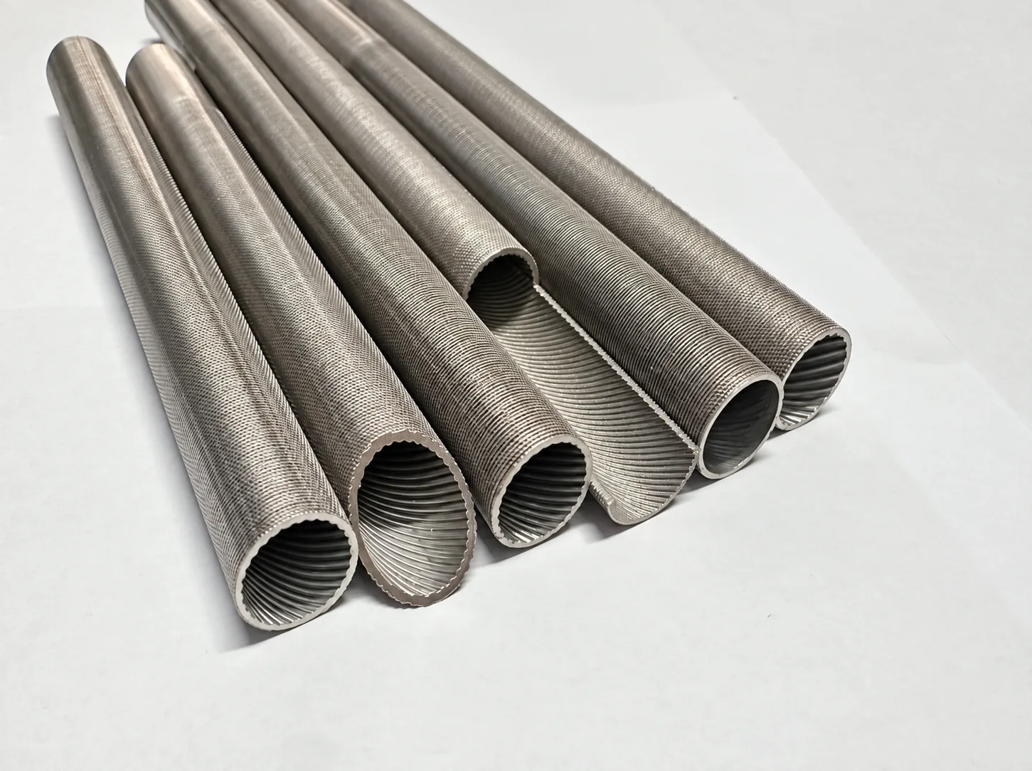
Catalogue photo · condenser reference specimens · Mixed profiles shown; confirm inner ribs on the selected tube.
Condenser tube / external condensation review
Enhanced Condenser Tubes
As an enhanced condenser tube manufacturer and supplier, GAOFA TECH forms externally finned and optionally notched profiles combined with internal helical ribs. The photo shows a range of reference samples; the drawing excerpt below identifies one specific 304L geometry.
Catalogue photo · evaporator reference specimens · Mixed profiles shown; confirm inner ribs on the selected tube.
Evaporator tube / phase-change review
Enhanced Evaporator Tubes
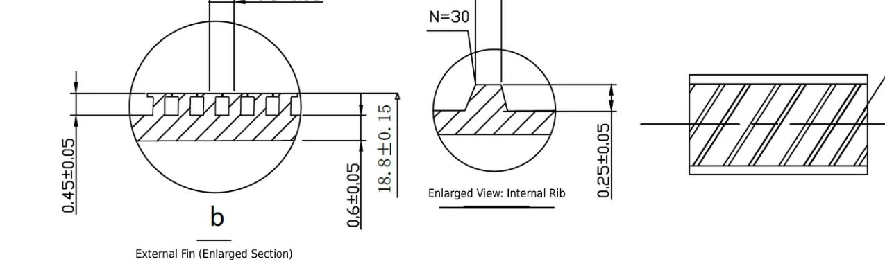
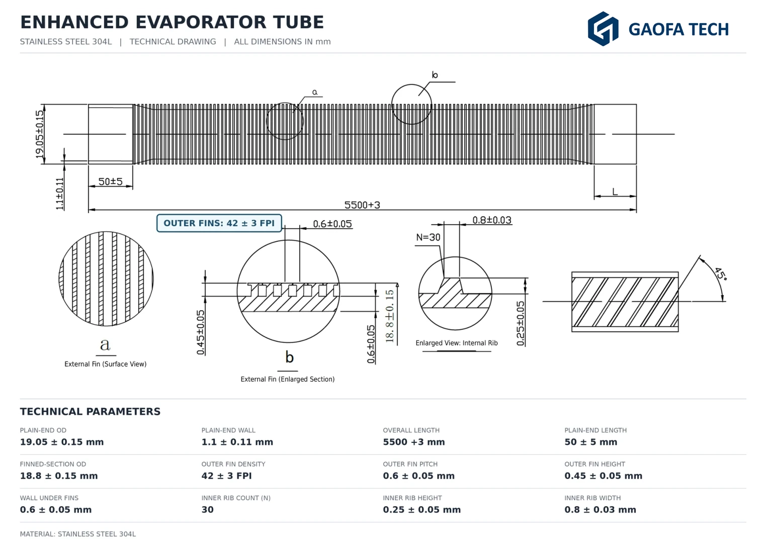
As an enhanced evaporator tube manufacturer and supplier, GAOFA TECH pairs externally structured fins with a specified internal-rib profile. The reference photo shows several tube designs; the drawing excerpt below identifies one specific 304L geometry.
Not a universal interchange: A condenser fin pattern is not automatically an optimized evaporator boiling surface. A change of refrigerant, boiling location, material or tube geometry may require separate thermal and mechanical validation. See condenser and evaporator tube selection ↗
05 / Geometry
Dual Enhanced Tube Dimensions and Drawing Requirements
Finished geometry should be defined using the original drawing, not just nominal OD and a generic “enhanced” description.
Plain-end OD (Do) & wall (To)
Starting / plain-end dimensions, tolerances, material and tube form.
Fin outside diameter (Df)
Measured over the finished fins; may differ from plain-end OD.
External fin height (Hf)
General catalogue direction up to 1.30 mm, profile dependent.
Fin pitch / FPI
General reference range 26–50 fins/inch; pitch and FPI must agree with drawing.
Remaining wall under fins
Specified independently of starting wall to protect tube integrity.
Internal rib count / height / helix
Count, height, width and angle are specified for internal enhancement.
Finned length, G & optional S
G = plain end. S = optional intermediate plain / skip-fin section; S can be omitted.
Overall length & inspection
General catalogue length up to 15 m; actual route, tolerances and testing by order.
Drawing-Based Geometry References
Reference examples from the two 304L drawings and one titanium Grade 2 drawing example, with the original drawing images for geometry verification. These do not constitute stock sizes.
Actual 304L drawing comparison
Condenser vs Evaporator: Same Base Size, Different Enhanced Geometry
Two supplied 304L drawings share Ø19.05 × 1.10 mm plain-end dimensions, 5,500 mm nominal length and 42 ± 3 FPI, but their external fin and internal rib details are not identical.
Drawing parameter
304L condenser
304L evaporator
Outer fin height
0.50 ± 0.05 mm
0.45 ± 0.05 mm
Wall under fins
0.65 ± 0.08 mm
0.60 ± 0.05 mm
Internal rib count
20
30
Internal rib height
0.20 ± 0.05 mm
0.25 ± 0.05 mm
External fin finish
Notched / knurled
External fin pattern per drawing
Drawing examples are for geometry comparison, not evidence of measured heat-transfer improvement, standard stock or universal material availability. The customer-approved drawing controls final tolerances.
Stainless steel 304L
Condenser reference
Drawing example
Plain OD × wall
19.05 × 1.10 mm
Overall length
5,500 mm
Outer fins
42 ± 3 FPI
Fin OD / height
18.8 / 0.50 mm
Wall under fins
0.65 mm
Internal ribs
20 × 0.20 mm high
Plain ends
50 ± 5 mm
Fin pitch
0.60 ± 0.05 mm
Inner rib height
0.20 ± 0.05 mm
Reference drawing includes notched / knurled outer fins. All tolerances follow the source drawing.
View the reference geometry; specifications and approvals follow the original drawing.Stainless steel 304L
Evaporator reference
Drawing example
Plain OD × wall
19.05 × 1.10 mm
Overall length
5,500 mm
Outer fins
42 ± 3 FPI
Fin OD / height
18.8 / 0.45 mm
Wall under fins
0.60 mm
Internal ribs
30 × 0.25 mm high
Plain ends
50 ± 5 mm
Fin pitch
0.60 ± 0.05 mm
Inner rib width
0.80 ± 0.03 mm
This drawing is not identical to the condenser profile. Different internal ribs and wall under fins.
View the reference geometry; specifications and approvals follow the original drawing.Titanium Grade 2
Dual-side proposal
Drawing example · feasibility review
Plain-end OD
19.05 mm
Plain-end wall
1.25 mm
Outer fins
36 FPI
Fin pitch
≈0.705 mm
Internal rib height
0.30 mm
Proposed lengths
3,000–6,000 mm
External fin height
0.30 ± 0.05 mm
Wall under fins
0.65 nominal; min 0.60 mm
Helix direction
45° proposal
Supplier-proposed geometry subject to customer approval, final tolerances and manufacturing confirmation.
View the reference geometry; specifications and approvals follow the original drawing.
Engineering tool / Geometric area
Compare the Theoretical Surface Area of Both Sides
Use our Enhanced Tube Surface Area Calculator to estimate the external fin area and, when the required rib geometry is defined, the internal helical-rib area separately. It is a geometry-screening tool, not a heat-transfer duty, coefficient or pressure-drop prediction. The two sides must not be added together as one effective heat-transfer area.
GAOFA TECH has complete in-house dual-enhancement manufacturing capability. Buyers looking for a double enhanced tube manufacturer or dual enhanced tube supplier can submit drawings for a defined combination of external fins, inner ribs, material and remaining wall.
01 · Base tube and material
Confirm material grade, plain-end OD / wall, and welded or seamless starting-tube route. Review the applicable finished-tube standard and base-tube specification separately. Heat-number traceability, any EN 10204 Type 3.1 inspection document and inspection scope depend on the purchase order, manufacturing route and material-source certification arrangements.
02 · In-house dual-side forming
Manufacture the agreed external low-fin or notched fin section together with the defined internal helical ribs. Check compatibility of both profiles and wall remaining below the fins.
03 · Geometry and integrity checks
Review fin OD, height, pitch / FPI, internal rib count and depth, helix angle, plain lands and agreed non-destructive or pressure tests (such as eddy current, hydrostatic or pneumatic testing). Inspection methods follow the order.
04 · Packing and export supply
Coordinate cut length, tube-end preparation, protection of enhanced surfaces, seaworthy export packing for shell-and-tube exchanger bundles and commercial documentation for the confirmed supply scope.
Relevant ASTM Standards: Finished Enhancement vs Base Tube
These are specification references for the applicable tube form and material—not a blanket claim that every drawing, size or inspection method is automatically covered. The purchase order must identify the applicable edition and agreed acceptance criteria.
Material
Relevant specification
What it covers
Stainless steel / alloy steel
ASTM A1012 Integral enhanced condenser / heat exchanger tubing
Cold-formed integral enhancement on the outside, inside, or both. Covers qualifying seamless or welded ferritic, austenitic and duplex alloy-steel tubes with unfinned end OD up to 25.4 mm (1 in.); boiler tubes are excluded. Where applicable, ASTM A213, A249 or A269 may be specified separately for the starting tube.
Titanium / titanium alloy
ASTM B338 Seamless and welded condenser / heat exchanger tubes
Reference for the titanium base tube, including applicable Grade 1 or Grade 2 tubing. External fins, internal ribs and remaining wall require separate drawing-defined dimensional and inspection requirements.
Covers seamless copper and copper-alloy tubes with cold-formed integral enhancement on the outside, inside, or both. It does not automatically cover welded tubes or separately attached fins. Material and forming feasibility require project review.
Scope boundary: The general 10–45 mm plain-end OD range shown above is a catalogue review range, not the scope of ASTM A1012. Stainless profiles above 25.4 mm plain-end OD must use a separately agreed applicable specification / drawing and acceptance criteria; do not describe them as ASTM A1012 compliant. TEMA requirements, when specified, relate to the exchanger design and do not replace the material or enhanced-tube specification.
Manufacturer and supplier position: GAOFA TECH has its own complete double enhanced tube manufacturing capability, covering defined enhancement on both the inner and outer tube surfaces. We manufacture and supply specification-based dual enhanced tubing; each material, base-tube route and profile combination requires separate feasibility review. Material, starting tube route, each geometry and inspection scope remain subject to the agreed drawing and order review; no universal production combination or test certification is implied.
07 / Request for quotation
Request a Dual / Double Enhanced Tube Quotation
Send a tube drawing or the principal dimensions. GAOFA TECH can review and quote complete internally and externally enhanced tube manufacturing against your specification.
Minimum information to start
Material grade, tube form, plain-end OD × wall × length, quantity and application are enough for an initial review. For quotation accuracy, add the fin drawing and internal rib profile when available.
Helpful additional details: fin OD, fin height, FPI, knurling, wall under fins, internal ridge count / height / helix angle, G / S lengths, medium on each side, temperature, pressure, inspection and packing requirements.
Product: Dual / Double Enhanced Heat Transfer Tube
Material Grade:
Tube Form (Welded / Seamless / To Confirm):
Plain-end OD × Wall × Overall Length:
Quantity:
Application (Condenser / Evaporator / Other):
External Fin OD / Height / FPI / Notching:
Internal Rib Count / Height / Helix Angle:
Minimum Wall Under Fins:
Plain Ends (G) / Total Skip Length (S):
Working Media / Pressure / Temperature:
Drawing / Specification / Inspection:
08 / Technical FAQ
Dual & Double Enhanced Tube FAQ
What is a dual enhanced tube, and is it the same as a double enhanced tube?
Yes. Dual enhanced, double enhanced and doubly enhanced heat transfer tubes describe tubing with defined enhancement on both the inside and outside surfaces. In this product scope, external fins or notched / knurled fins are combined with internal helical ribs. A smooth-bore externally finned tube is not double enhanced.
Is GAOFA TECH a dual enhanced tube manufacturer or supplier?
GAOFA TECH is both a manufacturer and supplier of dual enhanced heat transfer tubes and has its own complete dual-side enhancement manufacturing capability. Final geometry, material and tube production route are confirmed against the buyer’s drawing and agreed inspection requirements.
Which materials are available for double enhanced tubes?
Stainless steel grades 304, 304L and 316L are key enquiry directions; titanium Grade 1 and Grade 2 can be reviewed for suitable corrosion-resistant applications. For seamless copper or copper-alloy integral-fin tubing, ASTM B359/B359M may be relevant on a project basis. Not every geometry, material, tube route or dimensional combination is automatically available; drawings and manufacturing feasibility are reviewed before quotation.
What is the difference between dual enhanced condenser tubes and evaporator tubes?
The thermal duties and fluid-side phase-change mechanisms differ. External fin notching, fin height and pitch, internal rib geometry and remaining wall may therefore differ even at the same nominal tube OD. The supplied 304L condenser and evaporator drawings provide distinct examples rather than interchangeable standard designs.
Are internally ribbed and externally finned tubes necessarily more efficient?
Not necessarily. Geometric area alone does not establish heat-transfer duty. Tube-side and shell-side coefficients, fin efficiency, pressure drop, fouling, cleaning access, material and exchanger configuration must all be considered.
Can you make double enhanced tubes with plain ends and without intermediate skip-fin sections?
Yes, drawings can specify the required plain ends for tube-sheet connections and either continuous enhancement between the ends or additional intermediate smooth lands for supports. The locations and total lengths are defined by the equipment drawing.
Which dimensions matter most when buying from a dual enhanced tube manufacturer?
Please provide material, starting tube form, plain-end OD and wall, overall length, external fin OD / height / FPI, internal rib count / height / helix angle, minimum wall under fins, plain-end and optional skip lengths, tolerances, quantity and application. A cross-section drawing is particularly useful.
Can the tube surface area calculator confirm actual condenser or evaporator performance?
No. A surface-area calculator using idealized fin and rib profiles provides theoretical geometric estimates only. Real fin notching, radii, wall deformation and fluid-side heat-transfer effects require drawing-based review, CAD or suitable thermal analysis.
Explore related tube products
Enhanced Tube Products & Applications
Use the broader enhanced-tube page for general product types, or continue to materials, individual enhancement forms and condenser / evaporator applications.
The calculator compares theoretical internal and external geometric areas separately. It does not predict heat-transfer duty, fin efficiency or pressure drop.
Need a Dual Enhanced Tube Manufacturer for Your Drawing?
GAOFA TECH manufactures and supplies drawing-defined double enhanced tubing with external fin and internal rib profiles. Send the material, OD × wall × length, fin and groove geometry, quantity and application for a technical-commercial quotation.