A heating element fails after only a few months of service.
The process liquid is running at just 100°C, 120°C or 150°C.
The heater sheath is stainless steel, and the selected material should normally tolerate temperatures far above the process setpoint.
So why does the heater still fail?
The answer is often simple:
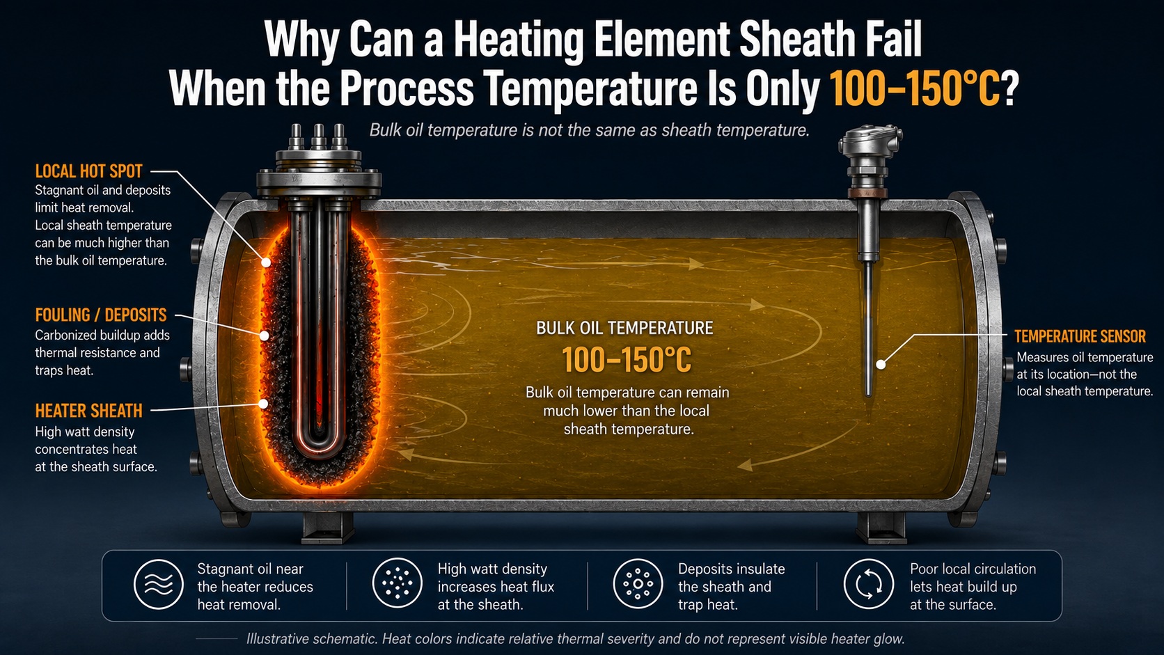
Process temperature is not the same as heater sheath temperature.
For tubular heating elements, especially those operating in oils or other relatively viscous liquids, the local thermal conditions directly around the heater can be much more severe than the temperature shown on the controller.
The 100-150°C range used in this article is only an illustrative process-temperature range. It is not a failure limit for SS304, Incoloy 800, Alloy 840 or any other sheath material.
A heater operating in a 120°C process can sometimes experience more severe local sheath conditions than another heater operating in a much hotter process – depending on watt density, circulation, fluid properties, geometry and surface condition.
This difference is one of the most important factors to understand when investigating premature tubular heater failure.
1. The Temperature Sensor Does Not Measure the Heater Sheath
In most tanks, the process temperature sensor is positioned somewhere in the liquid, often away from the heating element.
It measures the liquid temperature at the sensor location.
It does not directly measure the temperature of the heater sheath.
This distinction becomes particularly important when the liquid has limited circulation.
The bulk oil might be at 110°C while the thin layer of oil immediately surrounding the heater is considerably hotter.
The exact temperature difference cannot be determined from the bulk temperature alone. It depends on factors including:
- heater watt density,
- oil viscosity and thermal properties,
- circulation,
- heater geometry,
- heater spacing,
- surface deposits,
- oil condition,
- and operating cycle.
For thermal-oil systems, the difference between bulk-fluid temperature and local film temperature is well recognized. Excessive film temperature can accelerate thermal degradation and contribute to sludge or coke formation.
The important point is not that every thermal-oil system has the same temperature difference.
The important point is:
A low process temperature does not automatically mean a low heater sheath temperature.
2. Watt Density Is Often More Important Than Total kW
When evaluating an electric tubular heater, total power alone does not tell the full story.
A 3 kW heater can operate very differently from another 3 kW heater if their heated surface areas are different.
This is why heater designers pay close attention to watt density:
Watt density = heater power / active heated surface area
Consider two heaters producing the same total power.
If Heater A has twice the active heated surface area of Heater B, its surface watt density can be approximately half as high.
The liquid therefore has more surface area available to remove the same amount of heat.
This becomes especially important when heating oil.
Compared with water, many oils have lower heat-transfer capability, and their viscosity may increase significantly at lower temperatures.
This means that the most demanding condition may actually occur during cold start-up, when the oil is more viscous and local heat removal from the heater surface is less effective.
This is one reason oil-heating applications often use significantly lower watt densities than heaters designed for water or air.
There is no single universal watt-density limit for every oil application.
The acceptable value depends on:
- oil type,
- viscosity,
- operating temperature,
- flow velocity,
- heater geometry,
- vessel design,
- allowable film temperature,
- and expected service life.
For this reason, watt density should always be evaluated together with the actual operating conditions.
3. What Happens When Local Heat Removal Is Insufficient?
The failure mechanism can become self-reinforcing.
A typical sequence is:
High watt density or poor circulation
↓
Insufficient local heat removal
↓
Higher oil-film and sheath temperature
↓
Accelerated oil degradation
↓
Carbon, varnish or coke deposits develop on the heater
↓
Deposits increase thermal resistance
↓
Sheath temperature rises further
↓
Localized hot spot
↓
Premature heater failure
This is why a heater can fail even when the controller never shows an unusually high process temperature.
The controller may be doing exactly what it was designed to do – maintaining the liquid at 110°C or 130°C.
The problem may be occurring somewhere the controller is not directly measuring.
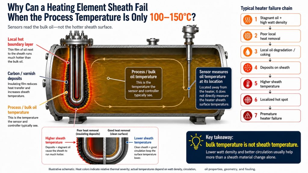
4. Deposits Are Not Only Evidence of Overheating – They Can Make Overheating Worse
Black carbonized material on a failed heater is often treated simply as evidence that the oil has degraded.
But deposits can also become part of the failure mechanism.
A clean heater transfers heat through a thermal path approximately like this:
Resistance wire → MgO insulation → metal sheath → liquid
Once deposits form, another layer is added:
Resistance wire → MgO insulation → metal sheath → deposit layer → liquid
That deposit layer can act as additional thermal resistance.
If heat transfer from the sheath into the liquid becomes less effective, the temperature gradient through the heater can increase.
This may push sheath and internal element temperatures higher.
A positive feedback loop can then develop:
higher local temperature → faster oil degradation → more deposits → poorer heat transfer → still higher local temperature
This is why simply replacing a failed heater without identifying the operating cause can result in the replacement heater eventually developing a similar failure.
5. “Stagnant Oil” Does Not Mean the Oil Never Moves
A tank without a circulation pump is often described as a stagnant-oil application.
Strictly speaking, however, the liquid may still move.
As oil near the heater warms, density changes can generate natural convection.
Warmer oil rises while cooler oil moves toward the heating area.
But natural convection is not the same as controlled forced circulation.
The liquid film immediately adjacent to the heater can still experience relatively poor heat transfer, particularly when:
- the oil is viscous,
- the heater watt density is high,
- heater elements are closely spaced,
- deposits have formed,
- vessel geometry restricts fluid movement,
- or the system repeatedly starts from a relatively low temperature.
Therefore, the engineering question should not simply be:
“Is the oil moving?”
A better question is:
“Can the liquid remove heat from the heater surface fast enough under the most demanding operating condition?”
6. Heater Spacing Also Matters
When several tubular elements are installed close together, each element does not operate in complete thermal isolation.
The oil surrounding one heater is also influenced by adjacent heaters.
If the elements are too closely spaced, the local thermal environment between them may become more severe.
In practical terms, the same total heater power can behave very differently depending on how that power is distributed.
For example:
6 kW concentrated into a relatively small heated surface
is not thermally equivalent to:
6 kW distributed over a substantially larger heated surface.
The second arrangement can have much lower watt density even though total power remains unchanged.
This is why reducing total kW is only one possible corrective action.
In many applications, a better engineering solution is:
increase effective heated surface area while maintaining the required total heating capacity.
This allows the required process power to be delivered with lower surface heat flux.
7. Will Changing SS304 to Incoloy 800 or Alloy 840 Solve the Problem?
This is where material selection needs to be separated from thermal design.
Suppose the existing heater uses an SS304 sheath.
If the process temperature is only 100-150°C, it may appear that SS304 should easily tolerate the application.
From the perspective of the bulk process temperature alone, that may be true.
But the sheath is exposed to its actual local operating temperature, not simply the temperature displayed by the process controller.
Changing to a higher-alloy sheath material can provide additional margin when actual sheath conditions become more severe.
For example, Incoloy 800 tube is commonly considered for heating elements and other applications where elevated-temperature performance and oxidation resistance are important.
Incoloy 840 tube is also widely used for electric heating element sheath applications, particularly where elevated-temperature oxidation resistance and heater-service performance are important.
For this reason, moving from SS304 to Incoloy 800 or Alloy 840 can sometimes improve heater durability.
But there is an important limitation:
Changing the sheath material does not reduce watt density.
If the heater operates at 8 W/cm² before the material change, it still operates at approximately 8 W/cm² afterward if power and active heated surface area remain unchanged.
Changing the sheath alloy also does not automatically:
- improve oil circulation,
- remove carbon deposits,
- increase heater spacing,
- reduce surface heat flux,
- lower oil viscosity,
- or correct temperature-sensor placement.
A higher-temperature alloy may tolerate the thermal condition better.
It does not remove the cause of that thermal condition.
This distinction is important:
Material upgrading increases tolerance.
Thermal redesign reduces the thermal stress itself.
Different nickel-alloy sheath materials also have different strengths and intended operating environments. If you are deciding between Incoloy 800, Incoloy 840 and Incoloy 825 for electric heating applications, see our detailed comparison:
Incoloy 800 vs Incoloy 840 vs Incoloy 825 for Heating Elements
That comparison looks more specifically at how these alloys differ in heating-element applications and why the “best” alloy depends on the actual service condition rather than temperature alone.
For a broader overview of available stainless-steel and nickel-alloy tubing for heater production, see our Heating Element Tubes application page.
8. What About Changing SS304 to SS316L?
If the dominant failure mechanism is local overheating and oil coking, changing from SS304 to SS316L would normally not be the first corrective action to investigate.
304 and 316L are both widely used stainless steel tube materials, but 316L is generally selected where its additional corrosion resistance is useful.
If the actual problem is excessive local heat flux and insufficient heat removal, changing from 304 to 316L does not fundamentally change that thermal condition.
This is why a material change should always answer a specific engineering question:
What failure mechanism are we trying to solve?
If the problem is corrosion, alloy chemistry may be critical.
If the problem is elevated-temperature oxidation or loss of sheath strength, a higher-temperature alloy may provide useful additional margin.
If the problem is excessive watt density and poor local heat transfer, thermal design should be addressed first.
Material selection should therefore be based on the actual combination of medium, temperature, corrosion condition and heater construction rather than temperature alone.
Our Tube Material Selection Guide provides a broader overview of these selection factors.
9. A Better Troubleshooting Sequence
When a tubular heater repeatedly fails in oil service, starting with material replacement may lead the investigation in the wrong direction.
A more useful sequence is:
Step 1 – Calculate the Actual Watt Density
Do not evaluate only the total kW.
Determine:
- active heated length,
- sheath diameter,
- active heated surface area,
- W/cm² or W/in².
The active heated length is particularly important because the entire physical length of a heater is not necessarily the electrically heated length.
Step 2 – Review the Worst Operating Condition
Do not evaluate only the final process temperature.
Consider:
- cold-start oil viscosity,
- initial oil temperature,
- heating cycle duration,
- number of heating cycles per day,
- oil ageing,
- minimum oil level,
- heater immersion,
- and temporary exposure during draining or filling.
The heater may experience its most demanding condition before the process ever reaches its final set temperature.
Step 3 – Review Circulation
Determine whether the system uses:
- forced circulation,
- mechanical agitation,
- natural convection only.
Then evaluate whether the heater arrangement allows adequate local fluid movement around the sheath.
Step 4 – Inspect Deposits
Heavy carbon or varnish should not simply be cleaned and ignored.
They may be evidence that local oil-film or sheath temperatures have already been excessive.
The location of the deposits can also provide useful information.
If deposits are concentrated around certain bends, closely spaced elements or particular sections of the heater, this may indicate a localized heat-transfer problem.
Step 5 – Review Temperature Sensing
Ask where the process sensor is located relative to the heater.
The sensor reading should not automatically be treated as the heater surface temperature.
For applications where sheath overheating is a significant risk, an independent high-limit device or additional temperature protection may also be considered as part of the overall heater-system design.
Step 6 – Review Sheath Material
Only after understanding the thermal condition should the designer decide whether SS304 remains appropriate or whether a higher-alloy material provides useful additional operating margin.
For projects where stainless steel is no longer sufficient, the wider range of nickel alloy tubes can be reviewed according to temperature, oxidation, corrosion and customer specification.
10. Lower kW or Larger Heating Surface?
Reducing heater power can work because it reduces watt density when the heater geometry remains unchanged.
For example:
If the same heater surface is changed from:
3 kW → 2 kW
then watt density decreases by approximately one third.
This can significantly reduce local thermal stress.
But it also reduces total heating capacity and usually increases heating time.
Where process cycle time matters, another approach may be more attractive:
maintain the required total kW while increasing the active heated surface area.
This may be achieved through:
- longer heated elements,
- additional heater elements,
- different element geometry,
- improved heater spacing,
- or a larger overall heating surface.
The objective is not simply to use the lowest possible kW.
The objective is to deliver the required process heat at an acceptable surface heat flux.
This leads to a better design question:
“How much heat can this heater surface safely transfer into this medium under the actual operating conditions?”
rather than simply:
“How many kilowatts does the process need?”
Material Upgrade vs Thermal Design
| Question | Material Upgrade | Lower Watt Density / Better Heat Transfer |
|---|---|---|
| Improves high-temperature sheath margin | Yes, depending on alloy | Indirectly, by lowering sheath temperature |
| Reduces watt density | No | Yes |
| Improves oil circulation | No | Can be addressed directly |
| Reduces overheating-related deposits | Not necessarily | Can reduce the underlying cause |
| Improves corrosion resistance | Depends on alloy | Usually no |
| Addresses local thermal overload | Usually not by itself | Often yes |
This distinction is critical.
A more heat-resistant sheath material can make a heater more tolerant of a difficult operating condition.
A better thermal design makes the operating condition less difficult in the first place.
Final Takeaway
When a tubular heater fails in a process running at only 100-150°C, the first question should not be:
“Can SS304 withstand 150°C?”
The better questions are:
What is the actual heater sheath temperature?
What is the watt density?
How effectively is heat being removed from the heater surface?
What happens during cold start-up?
Is there forced circulation, natural convection or almost no effective local flow?
Are deposits increasing thermal resistance?
Where is the temperature sensor located?
Only after these questions are understood does it make sense to ask whether the sheath should remain SS304 or be upgraded to Incoloy 800, Alloy 840 or another material.
For tubular heating elements, long service life depends on the interaction of:
watt density + heat transfer + circulation + geometry + surface condition + operating cycle + sheath material
not simply the process temperature shown on the controller.
Bulk temperature is not sheath temperature.